Welding device

A welding device and welding head technology, applied in the field of welding, can solve the problems of hidden danger of welding machine, complicated operation steps, easy to scratch people, etc., and achieve the effects of high safety, simple device structure and stable welding operation.

Active Publication Date: 2017-08-29
浙江汇杰制冷设备有限公司
View PDF6 Cites 0 Cited by
  • Summary
  • Abstract
  • Description
  • Claims
  • Application Information

AI Technical Summary

Problems solved by technology

[0002] With the popularity of metal or other thermoplastic materials, more and more welding machines are used. Welding is a manufacturing process that connects metal or other thermoplastic materials by means of heating, high temperature, and high pressure. In the process of welding, It is usually necessary to fix the welded parts separately first, and then perform the welding operation. The operation steps are cumbersome, and the welding head is usually exposed, which is easy to scratch people during the welding process, or people accidentally turn on the welding machine when it is not in use. The welding head is easy to scratch people, so the traditional welding machine has potential safety hazards

Method used


Image

  • Welding device
  • Welding device
  • Welding device

Examples


Embodiment Construction

[0018] All features disclosed in this specification, or steps in all methods or processes disclosed, may be combined in any manner, except for mutually exclusive features and / or steps.

[0019] Any feature disclosed in this specification (including any appended claims, abstract and drawings), unless expressly stated otherwise, may be replaced by alternative features which are equivalent or serve a similar purpose. That is, unless expressly stated otherwise, each feature is one example only of a series of equivalent or similar features.

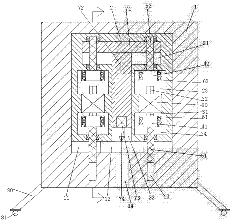
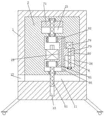
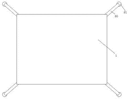
[0020] Such as Figure 1-3 As shown, a welding device of the present invention includes an outer frame 1, the bottom of the outer frame 1 is provided with a supporting foot 80, and the supporting foot 80 is arranged obliquely to increase stability, and the bottom of the supporting foot 80 is provided with Universal wheel 81, a sliding cavity 11 is arranged in the outer frame, a sliding frame 2 is installed in the sliding cavity 11 to slide up...


PUM


Abstract

The invention discloses a welding device. The welding device comprises an outer frame, wherein supporting legs which are arranged in an inclined mode are arranged on the bottom of the outer frame; universal wheels are arranged on the bottoms of the supporting legs; a sliding cavity is arranged in the outer frame; a sliding frame can be mounted in the sliding cavity in an up-down sliding mode; a first sliding slot with a downward mouth part is formed at a middle point of the sliding frame; the position, at the upper end of the first sliding slot, in the sliding frame is equipped with a second sliding slot which communicates with the first sliding slot; a top plate can be mounted in the second sliding slot in the up-down sliding mode; a lifting rod can be mounted in the first sliding slot in the up-down sliding mode; the upper end of the lifting rod is fixedly connected with the top plate; the lower end of the lifting rod is fixedly equipped with a first motor; the lower end of the first motor is connected with a welding head; an upper mounting slot and a lower mounting slot are symmetrically formed left and right in the sliding frame; a second motor is fixedly mounted between the upper mounting slot and the lower mounting slot; the upper end and the lower end of the second motor are separately connected with an upper movable shaft and a lower movable shaft; and a connecting slot which is formed in the rear end of the second motor and is used for connecting the upper mounting slot to the lower mounting slot is formed between the upper mounting slot and the lower mounting slot.

Description

technical field [0001] The invention relates to the field of welding, in particular to a welding device. Background technique [0002] With the popularity of metal or other thermoplastic materials, more and more welding machines are used. Welding is a manufacturing process that connects metal or other thermoplastic materials by means of heating, high temperature, and high pressure. In the process of welding, It is usually necessary to fix the welded parts separately first, and then perform the welding operation. The operation steps are cumbersome, and the welding head is usually exposed, which is easy to scratch people during the welding process, or people accidentally turn on the welding machine when it is not in use. The welding head is easy to scratch people, so the traditional welding machine has potential safety hazards. Contents of the invention [0003] The object of the present invention is to provide a welding device and its use method, which can overcome the abo...

Claims


Application Information

Patent Timeline
Patent Type & Authority Applications(China)
IPC IPC(8): B23K37/00B23K37/04
CPCB23K37/006B23K37/0443
Inventor 刘建华
Owner 浙江汇杰制冷设备有限公司
Why Eureka
Try Eureka