Lifting type multi-layer clamp storage rack

A storage rack and lift-type technology, applied in the field of storage racks, can solve the problem that the partition cannot be lifted independently.

Inactive Publication Date: 2017-09-12
YANGTZE NORMAL UNIVERSITY
View PDF4 Cites 3 Cited by
  • Summary
  • Abstract
  • Description
  • Claims
  • Application Information

AI Technical Summary

Problems solved by technology

[0004] Aiming at the deficiencies of the above-mentioned prior art, the present invention provides a lift-type multi-layer fixture storage rack, which solves the technical problem that the partitions in the fixture storage

Method used


Image

  • Lifting type multi-layer clamp storage rack
  • Lifting type multi-layer clamp storage rack
  • Lifting type multi-layer clamp storage rack

Examples


specific Embodiment approach 1

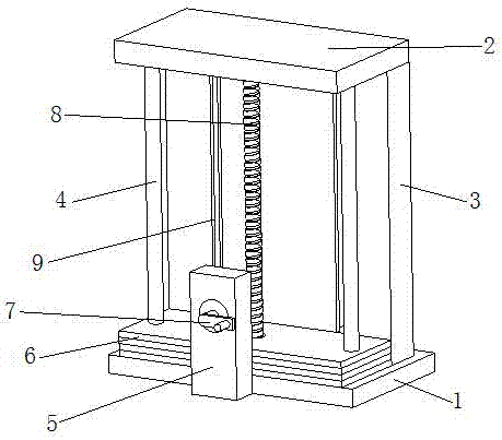
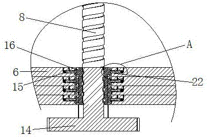
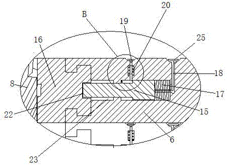
[0027] Such as Figure 1 to Figure 5 As shown, a lifting type multi-layer clamp storage frame includes a base plate 1, a top plate 2, a screw rod 8 and a plurality of swivel sleeves 16 that are threaded on the screw rod 8 and threaded therewith; the upper and lower ends of the screw rod 8 are respectively connected to The top plate 2 and the bottom plate 1 are rotationally connected; each swivel sleeve is sleeved with a partition 6; the outer peripheral surface of the swivel sleeve 16 is provided with an annular tenon, and the partition 6 is provided with an annular groove, and the annular tenon Embedded in the annular groove to limit the axial position of the partition 6; the partition 6 and the swivel sleeve 16 form a rotational connection through the cooperation of the annular tenon and the annular groove; the outer peripheral surface of the annular tenon of the swivel sleeve 16 There is a card groove 22 on the top; a guide groove 23 is arranged symmetrically about the scre...

specific Embodiment approach 2

[0041] The difference between this specific embodiment and specific embodiment 1 is that the structure of the pulling mechanism used to pull the clamping shaft 15 is different, specifically: the pulling mechanism includes a horizontal pull rod connected to the rear end surface of the clamping shaft 15, and a The horizontal via hole on the plate communicates with the rear end of the guide groove; the horizontal pull rod passes through the horizontal via hole and protrudes out of the partition, and the protruding end is connected with a pull ring. In this way, the pull rod has high strength, is not easy to be broken, and can prolong the service life.


PUM


Abstract

The invention discloses a lifting type multi-layer clamp storage rack. The lifting type multi-layer clamp storage rack comprises a bottom plate, a top plate, a screw and multiple swivel sleeves which are arranged on the screw in a penetrating and sleeving manner and are in threaded connection with the screw. Each partition plate and the corresponding swivel sleeve are rotationally connected through the cooperation manner of an annular tenon and an annular groove. A clamp groove is formed in the outer circumferential face of the annular tenon of each swivel sleeve. Guide grooves are formed in each partition plate symmetrically about the axis of the screw. A clamp shaft is connected in each guide groove in a sliding manner, and a limiting block is arranged on the upper surface of each clamp shaft. A limiting hole is formed in the upper surface of each partition plate. A limiting rod is connected in each limiting hole in a sliding manner. The lower end of each limiting rod can stretch out of the corresponding limiting hole and can stop the limiting block on the corresponding clamp shaft, and therefore each clamp shaft can keep the state of being separating from the corresponding clamp groove. A thrust spring is arranged in the rear end of each guide groove, and each clamp shaft can keep the state of being clamped in the corresponding clamp groove. A pull mechanism is connected to the rear end of each clamp shaft and can pull the clamp shaft to slide. According to the lifting type multi-layer clamp storage rack, the partition plates can ascend and descend correspondingly and do not influence one another, and the distance between the partition plates can be adjusted according to the clamp height.

Description

technical field [0001] The invention relates to a storage rack for storing clamps. Background technique [0002] The manufacturing of mechanical products plays a vital role in the development of a country. Due to the complex product structure and process of the mechanical manufacturing industry, a large number of fixtures will be designed during engineering design. The fixtures can be used with lathes, milling machines and other machines to process various shapes. However, due to the large difference in the shape and size of the fixture, the placement of the fixture has become a big problem. If the fixture is placed on the table, it will take up a lot of space. In the prior art, in order to save the space for placing the fixtures, a storage rack with multi-layer partitions is used. Since the partitions are fixed on the frame body, when placing the partition fixtures, when the middle and lower partitions are full , It is necessary to transport the fixture to the high-rise pa...

Claims


Application Information

Patent Timeline
IPC IPC(8): B25H3/04
CPCB25H3/04
Inventor 黎方军王涛
Owner YANGTZE NORMAL UNIVERSITY
Why Eureka
Try Eureka