a water conservancy equipment

An equipment and water conservancy technology, applied in the field of water conservancy equipment, can solve the problems of troublesome maintenance and replacement, time-consuming and laborious, and achieve the effects of convenient operation, improved installation stability, and increased installation speed.

Inactive Publication Date: 2018-05-25
NANJING HYDRAULIC RES INST +3
View PDF6 Cites 0 Cited by
  • Summary
  • Abstract
  • Description
  • Claims
  • Application Information

AI Technical Summary

Problems solved by technology

When the water level of the river is high but still needs to speed up drainage, drainage equipment is needed, and drainage paddles are one of them. Drainage paddles can be installed at pipe mouths, drainage outlets, etc. Low pressure speeds up the flow of water to the low-pressure area. Since the drainage blades are generally fixed by bolts and other fixed parts, maintenance and replacement are troublesome and time-consuming.

Method used


Image

  • a water conservancy equipment
  • a water conservancy equipment
  • a water conservancy equipment

Examples


Embodiment Construction

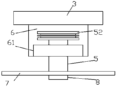
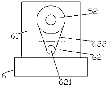
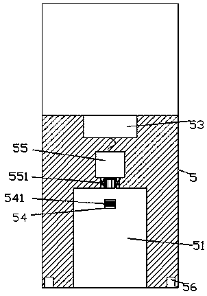
[0026] Such as Figure 1-Figure 9 As shown, a water conservancy equipment of the present invention includes a accommodating cavity 6 provided with a mounting portion 3 on the rear side of the accommodating cavity 6, and a column 61 is fixed on the front side of the top surface of the accommodating cavity 6. 61. The inner rotary fitting is connected with a rotary fixed lock shaft 5 extending forward and backward, and a sliding cavity 51 is provided in the front side extension of the rotary fixing shaft 5, and an inner rotary lock is arranged in the back wall of the sliding cavity 51 Rotating shaft 551, the rear end of the inner fixed locking rotary shaft 551 is matedly connected with the fixed locking electric rotary machine 55, the rotary fixed locking shaft 5 on the rear side of the fixed locking electric rotary machine 55 is provided with a power connection 53, the rotary fixed locking The front end of the shaft 5 is provided with a sliding-fitting connection fixing member 8 ...


PUM


Abstract

The invention discloses water conservancy equipment. The equipment comprises a containing cavity, a mounting part is arranged on the rear side of the containing cavity, and a column body is fixedly arranged on the front side of the top surface of the containing cavity; a gyratory fixing locking shaft extending towards front and back is connected in the column body in a gyratory and matched mode, a sliding cavity is formed in the extending end of the front side of the gyratory fixing locking shaft, and an internal fixing locking rotary shaft is matched in the rear side wall of the sliding cavity in a gyratory mode; the rear end of the internal fixing locking rotary shaft is connected with a fixing locking electric rotator in a matched mode, and an energization part is arranged in the position, on the rear side of the fixing locking electric rotator, of the gyratory fixing locking shaft; a fixing locking part is connected to the front end of the gyratory fixing locking shaft in a sliding and matched mode, and the fixing locking part comprises an external locking part, a first protruding block, a first inserting locking rod and a second inserting locking rod, wherein the first protruding block is fixed to the rear side of the external locking part, the first inserting locking rod is fixed to the periphery, outside the first protruding block, of the rear side of the external locking part, and the second inserting locking rod is fixed to the rear side of the first protruding block. According to the water conservancy equipment, the structure is simple, fixing locking installation can be quickly conducted, and the discharging process is accelerated.

Description

Technical field [0001] The invention relates to the technical field of water conservancy, and a water conservancy equipment. Background technique [0002] Water conservancy construction is one of the important basic public projects in our country. Over the past year, there have been frequent sudden rainstorms in various places, urban waterlogging is very serious, and the river drainage system is overwhelmed. When the water level of the river is high but the drainage still needs to be accelerated, drainage equipment is needed. The drainage paddle is one of them. The drainage paddle can be installed in the pipe mouth, drainage outlet, etc. The drainage paddle is formed by rotating on one side. Low pressure speeds up the flow of water to the low pressure area. Because the drainage blades are generally fixed by bolts and other fixed parts, it is troublesome to repair and replace, and it takes time and effort. Summary of the invention [0003] The technical problem to be solved by the...

Claims


Application Information

Patent Timeline
Patent Type & Authority Patents(China)
IPC IPC(8): E03F1/00E05B65/00
CPCE03F1/00E03F2201/30E05B65/00
Inventor 刘永志张文婷
Owner NANJING HYDRAULIC RES INST
Why Eureka
Try Eureka