Industrial waste gas treatment apparatus

A treatment device and industrial waste gas technology, which is applied in the direction of gas treatment, coupling devices, parts of connection devices, etc., can solve the problems of troublesome maintenance and replacement, delaying the normal operation of waste gas treatment, time-consuming and labor-intensive problems, etc., and achieves convenient and automatic operation. Fast installation and locking work, the effect of improving the stability of the installation

Inactive Publication Date: 2019-01-04
CHENGDU ZHILIDA TECH
View PDF5 Cites 0 Cited by
  • Summary
  • Abstract
  • Description
  • Claims
  • Application Information

AI Technical Summary

Problems solved by technology

[0002] Industrial sites often produce a large amount of industrial waste gas, such as powder waste gas particles, flue gas smoke waste gas, odorous gas, toxic and harmful gases, etc. Therefore, purification measures should be taken before being discharged into the atmosphere to make it meet the standards of waste gas discharge. The fan blades inside the industrial waste gas treatment device are generally fixed by screws, so it is very troublesome to repair and replace, and it takes time and effort to delay the normal progress of the waste gas treatment work.

Method used


Image

  • Industrial waste gas treatment apparatus
  • Industrial waste gas treatment apparatus
  • Industrial waste gas treatment apparatus

Examples


Embodiment Construction

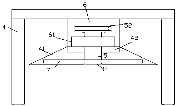
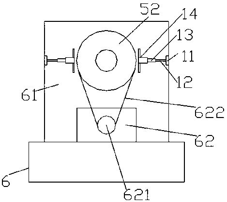
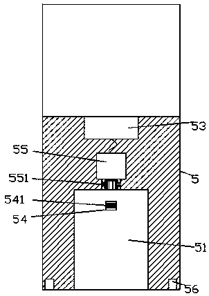
[0027] Such as Figure 1-Figure 9 As shown, an industrial waste gas treatment device of the present invention includes a frame body 4 and a cavity 6 arranged on the upper bottom surface of the frame body 4, a gas collection hood 41 is arranged below the cavity 6, and the gas collection hood 41 is provided with a processor 42 on the top surface, and the bottom of the cavity 6 is fixed with a square column 61, and the transfer lock shaft 5 is connected to the front and rear of the square column 61, and the transfer lock A sliding connection cavity 51 is provided in the extension tail tip of the front side of the connecting shaft 5, and an inner connecting shaft 551 is fitted in the rear side wall of the sliding connecting cavity 51, and the rear end of the inner connecting shaft 551 is locked to the driving device 55 For mating connection, a power-on block 53 is provided inside the transfer lock shaft 5 on the rear side of the lock drive device 55, and a lock assembly 8 is provi...


PUM


Abstract

An industrial waste gas treatment apparatus is disclosed, which comprises a frame body and a containing cavity arranged on the bottom surface of the frame body, a lower part of the containing cavity is provided with a gas collecting cover, a processor is arranged on the top surface in the gas collecting cover, the bottom of the containing cavity is provided with a square column, an adapter lockingshaft which is elongated forward and backward is adapted in the square column, a sliding connection cavity is arranged in the elongated tail tip of the front side of the adapter locking shaft, an inner adapter shaft is arranged in the rear side wall of the sliding connection cavity in an adapting matching mode, a rear end of the inner adapter shaft is cooperatively connected with a locking driving device, a powering-on block is arranged in an adapter locking shaft at the rear side of the locking driving device, a locking assembly is provided at the front end of the adapter locking shaft in sliding matching connection, the locking assembly comprises a back plate, a first convex end block fixed on the rear side of the back plate, a first plug rod fixed on the periphery of the rear side of the back plate on the outside of the first convex end block, and a second plug rod fixed on the rear side of the first convex end block. The invention has a simple structure, can quickly lock and install, and improves the processing process.

Description

technical field [0001] The invention relates to the technical field of waste gas treatment, and relates to an industrial waste gas treatment device. Background technique [0002] Industrial sites often produce a large amount of industrial waste gas, such as powder waste gas particles, flue gas smoke waste gas, odorous gas, toxic and harmful gases, etc. Therefore, purification measures should be taken before being discharged into the atmosphere to make it meet the waste gas emission standards. The fan blades inside the industrial waste gas treatment device are generally fixed by screws, so it is very troublesome to repair and replace, and it takes time and effort to delay the normal progress of the waste gas treatment work. Contents of the invention [0003] The technical problem to be solved by the present invention is to provide an industrial waste gas treatment device, which can solve the above-mentioned problems in the prior art. [0004] The present invention is achie...

Claims


Application Information

Patent Timeline
Patent Type & Authority Applications(China)
IPC IPC(8): H01R13/627H01R13/629B01D53/00
CPCH01R13/6278B01D53/00B01D2258/02H01R13/627H01R13/629
Inventor 郑杰
Owner CHENGDU ZHILIDA TECH
Why Eureka
Try Eureka