Environment-friendly waste gas treatment device

An exhaust gas treatment device and an environmentally friendly technology, which is applied to the separation of dispersed particles, chemical instruments and methods, and separation methods, can solve problems such as troublesome maintenance and replacement, time-consuming and labor-intensive delays, and delays in the normal operation of exhaust gas treatment. It achieves convenient operation and improved The effect of installation stability, automatic and quick installation and locking work

Inactive Publication Date: 2018-12-25
CHENGDU ZHILIDA TECH
View PDF5 Cites 0 Cited by
  • Summary
  • Abstract
  • Description
  • Claims
  • Application Information

AI Technical Summary

Problems solved by technology

[0002] Industrial sites often produce a large amount of industrial waste gas, such as powder waste gas particles, flue gas smoke waste gas, odorous gas, toxic and harmful gases, etc. Therefore, purification measures should be taken before being discharged into the atmosphere to make i

Method used


Image

  • Environment-friendly waste gas treatment device
  • Environment-friendly waste gas treatment device
  • Environment-friendly waste gas treatment device

Examples


Embodiment Construction

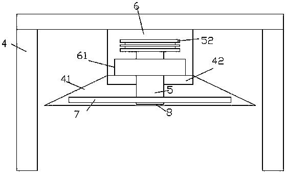
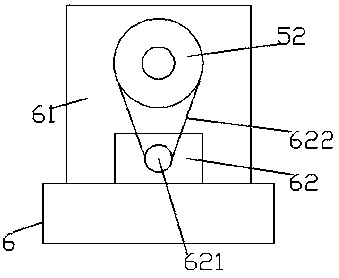
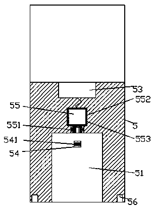
[0027] Such as Figure 1-Figure 9 As shown, an environmentally friendly exhaust gas treatment device of the present invention includes a frame body 4 and a cavity 6 arranged on the upper bottom surface of the frame body 4, a gas collection cover 41 is arranged below the cavity 6, and the gas collection A processor 42 is arranged on the inner top surface of the cover 41, and a square column 61 is fixedly arranged at the bottom of the cavity 6, and a transfer locking shaft 5 extending forward and backward is connected to the inside of the square column 61. A sliding connection cavity 51 is provided in the elongated tail tip on the front side of the locking shaft 5, and an inner connecting shaft 551 is fitted in the rear side wall of the sliding connecting cavity 51, and the rear end of the internal connecting shaft 551 is connected with the locking drive device. 55 to connect with each other, the transfer lock shaft 5 on the rear side of the lock drive device 55 is provided with...


PUM


Abstract

The invention discloses an environment-friendly waste gas treatment device which comprises a frame and a chamber. The chamber is arranged on the upper bottom surface of the frame, a gas collecting hood is arranged on the lower side of the chamber, a treater is arranged on the inner top surface of the gas collecting hood, a square column is fixedly arranged at the bottom of the chamber, a through collection locking shaft which is arranged in a forward and backward extension manner is connected into the square column in a through manner, a slide connection cavity is arranged in an extension tailon the front side of the through collection locking shaft, an inner through connection shaft is fittingly connected into the rear side wall of the slide connection cavity in a through manner, the rear end of the inner through connection shaft is fittingly connected with a locking driving device, a power-on block is arranged on the rear side of the locking driving device and is positioned in the through connection locking shaft, a locking assembly which is slidably fittingly connected with the through connection locking shaft is arranged at the front end of the through connection locking shaftand comprises a back plate, a first convex end block, first insertion rods and a second insertion rod, the first convex end block is fixed to the rear side of the back plate, the first insertion rodsare fixed to the outer side of the first convex end block and are positioned on the periphery of the rear side of the back plate, and the second insertion rod is fixed to the rear side of the first convex end block. The environment-friendly waste gas treatment device has the advantages that the environment-friendly waste gas treatment device is simple in structure and can be quickly locked and mounted, and treatment processes can be improved.

Description

technical field [0001] The invention relates to the technical field of waste gas treatment, and relates to an environment-friendly waste gas treatment device. Background technique [0002] Industrial sites often produce a large amount of industrial waste gas, such as powder waste gas particles, flue gas smoke waste gas, odorous gas, toxic and harmful gases, etc. Therefore, purification measures should be taken before being discharged into the atmosphere to make it meet the waste gas emission standards. The fan blades inside the environmentally friendly exhaust gas treatment device are generally fixed by screws, so it is very troublesome to repair and replace, and it takes time and effort to delay the normal progress of the exhaust gas treatment work. Contents of the invention [0003] The technical problem to be solved by the present invention is to provide an environmentally friendly waste gas treatment device, which can solve the above-mentioned problems in the prior art...

Claims


Application Information

Patent Timeline
IPC IPC(8): B01D53/00
CPCB01D53/00
Inventor 郑杰
Owner CHENGDU ZHILIDA TECH
Why Eureka
Try Eureka