Optical flat structure achieving air imaging

An optical flat and imaging technology, applied in the optical field, can solve the problems of low practicability, insufficient display effect and interactive experience, and large energy loss, etc., to achieve the effect of simple structure

Pending Publication Date: 2017-09-22
ANHUI EASPEED TECHNOLOGY CO LTD
View PDF10 Cites 14 Cited by
  • Summary
  • Abstract
  • Description
  • Claims
  • Application Information

AI Technical Summary

Problems solved by technology

[0002] At present, the air imaging method that can be realized on the market is to spray water vapor in the air, and the water vapor liquefies into small water droplets to form a fog screen on the whole, and then project the content onto the fog screen to realize air imaging, but In essence, it is still a projection method, and continuous water supply is required to continuously form a fog screen. At the same time, the image formed by projection will have serious light loss, the imaging effect is extremely poor, and the energy loss in the whole process is also huge. , the practicability is small, and it cannot be a substitute for the next generation of display devices
[0003] At present, there are many products at home and abroad that use interference and diffraction to realize holographic imaging step by step and display them. The design methods are various, but there are also some shortcomings. The existing holographic projection products must be imaged on a specific carrier, and the effect is poor. It is a "pseudo" hologram, and the display effect and interactive experience are not attractive enough for the product

Method used


Image

  • Optical flat structure achieving air imaging
  • Optical flat structure achieving air imaging
  • Optical flat structure achieving air imaging

Examples


Embodiment Construction

[0015] A preferred embodiment of the present invention will be described in detail below with reference to the accompanying drawings.

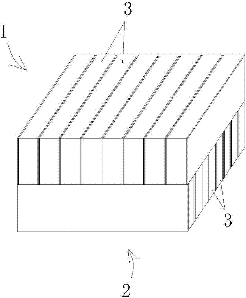
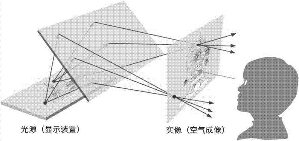
[0016] Such as figure 1 As shown, the optical flat plate structure for realizing air imaging includes an upper layer lens 1 and a lower layer lens 2 that are tightly bonded and stacked. Both the upper layer lens and the lower layer lens use a plurality of reflective strips 3 arranged in parallel. The reflective strips are perpendicular to the surface of the lens, and the upper layer The reflective strips of the lens and the reflective strips of the lower lens are arranged orthogonally to form a two-layer neatly arranged orthogonal mirror structure. The scattered light emitted by any point light source, plane light source and three-dimensional light source will pass through the lens with this special structure. The same position on the other side of the lens re-converges the image, refer to image 3 and 5 .

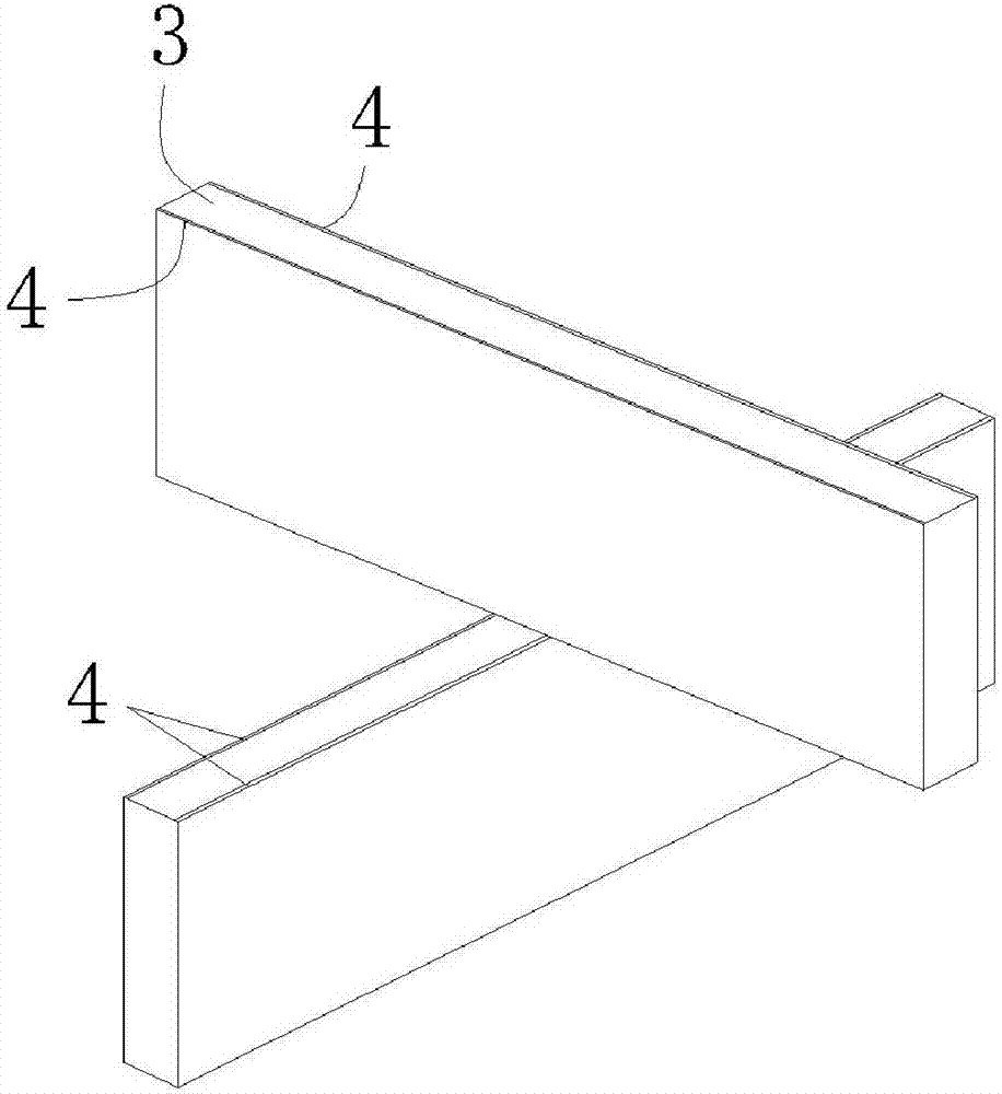
[0017] Such as figure 2 As sho...


PUM


Abstract

The invention provides an optical flat structure achieving air imaging. The optical flat structure is characterized by comprising an upper lens and a lower lens which are overlaid in a closely attached mode; the upper lens and the lower lens are both formed by multiple reflecting bars which are perpendicular to the lens surface and arranged in parallel, reflecting films are arranged on the two side faces of each reflecting bar respectively, and the reflecting bars of the upper lens and the reflecting bars of the lower lens are arranged in an orthogonal mode. According to the optical flat structure, through an optical panel reconstructed through a special precise microstructure, a two-dimensional or three-dimensional light source can form a real image in air directly to realize a real holographic image; the structure is simple, a real image can be directly formed before a user's eyes, and real holographic interaction can be achieved through system integration in the later stage.

Description

technical field [0001] The invention relates to the field of optical technology, in particular to an optical flat plate structure for realizing air imaging. Background technique [0002] At present, the air imaging method that can be realized on the market is to spray water vapor in the air, and the water vapor liquefies into small water droplets to form a fog screen on the whole, and then project the content onto the fog screen to realize air imaging, but In essence, it is still a projection method, and continuous water supply is required to continuously form a fog screen. At the same time, the image formed by projection will have serious light loss, the imaging effect is extremely poor, and the energy loss in the whole process is also huge. , the practicability is small, and it cannot become the next-generation display device substitute. [0003] At present, there are many products at home and abroad that use interference and diffraction to realize holographic imaging s...

Claims


Application Information

Patent Timeline
Patent Type & Authority Applications(China)
IPC IPC(8): G02B27/00G02B27/01
CPCG02B27/00G02B27/0101
Inventor 范超韩东成张亮亮李正军黄志刚
Owner ANHUI EASPEED TECHNOLOGY CO LTD
Why Eureka
Try Eureka