Elevator protective plate and method for assembling the protective plate
An assembly method and protection plate technology, which is applied in transportation, packaging, elevators, etc., can solve the problems of labor-intensive operators, time-consuming installation of protective plates, and many operating procedures.
- Summary
- Abstract
- Description
- Claims
- Application Information
AI Technical Summary
Problems solved by technology
Method used
Image
Examples
Embodiment approach 1
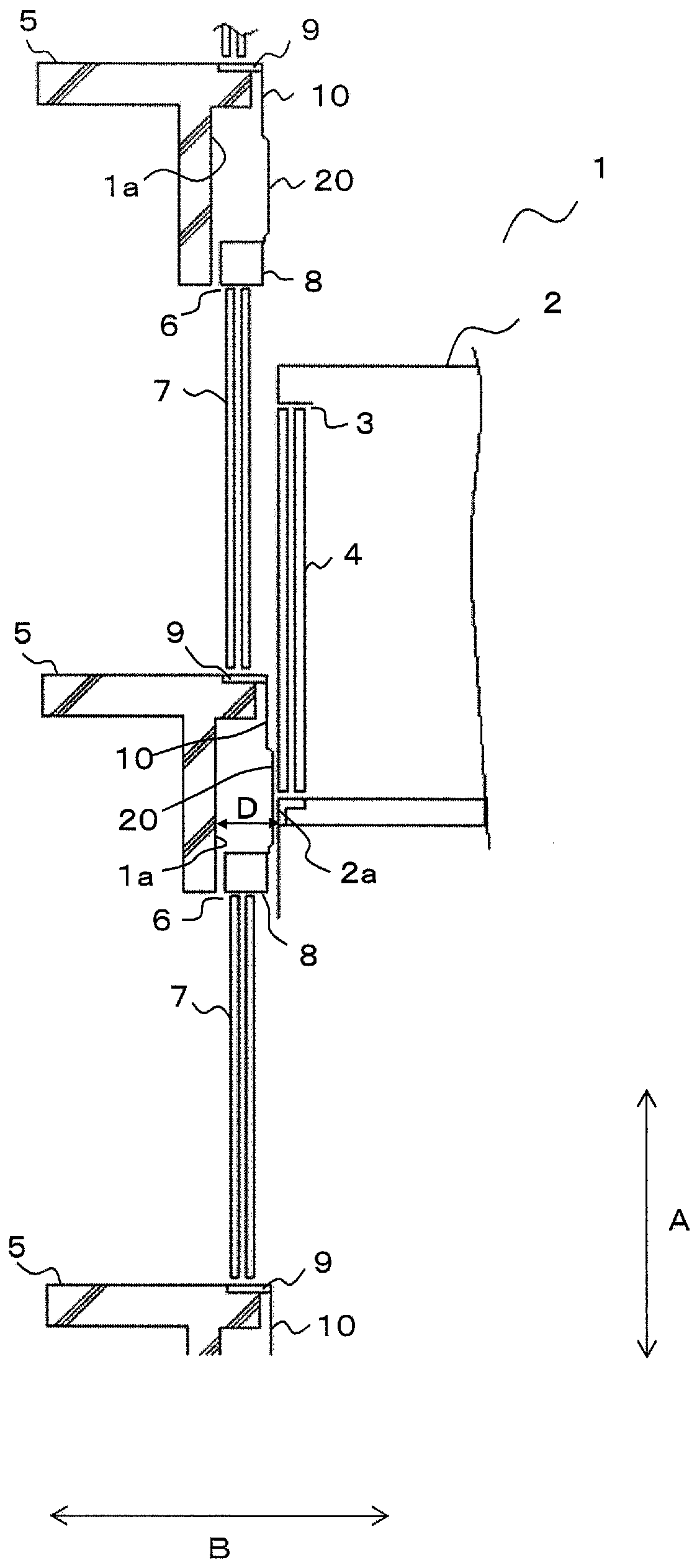
[0028] figure 1 It is an overall view showing an elevator provided with an elevator protective panel according to Embodiment 1 of the present invention. Such as figure 1 As shown, a car 2 is provided in the hoistway 1, and the car 2 is guided by a guide rail (not shown) provided in the hoistway 1 so as to be movable in the vertical direction. Additionally, the figure 1 The direction of the arrow A is called the height direction of the hoistway 1, and the direction of the arrow B is called the depth direction of the hoistway 1.
[0029] The car 2 is provided with a car doorway 3 allowing a user to enter and exit the car 2 . A car door 4 that can be freely opened and closed is provided at the car entrance 3 .
[0030] On the surface facing the car door 4 in the depth direction, halls 5 for each floor are provided. The hall door 7 is provided in the hall entrance 6 of the hall 5 of each floor so that opening and closing is possible. The landing door 7 can be moved along the...
Embodiment approach 2
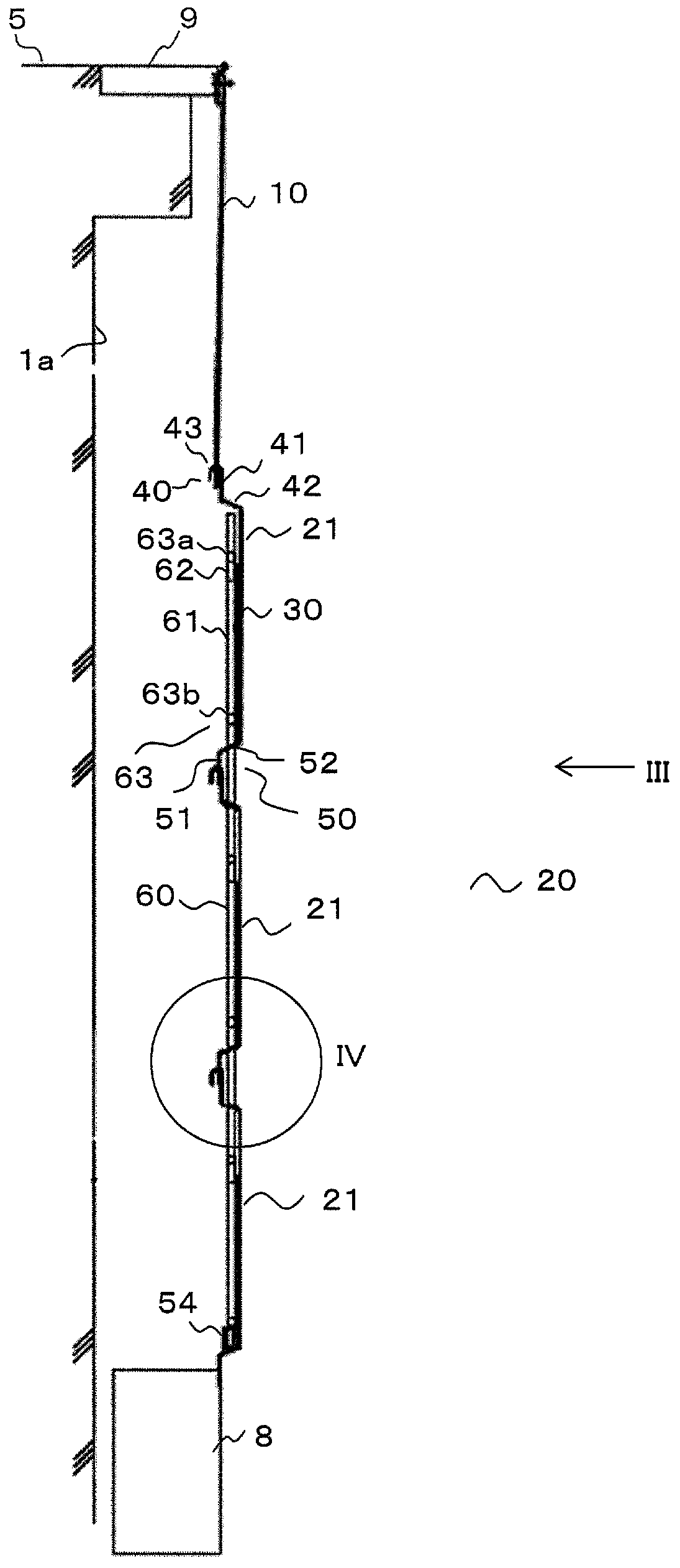
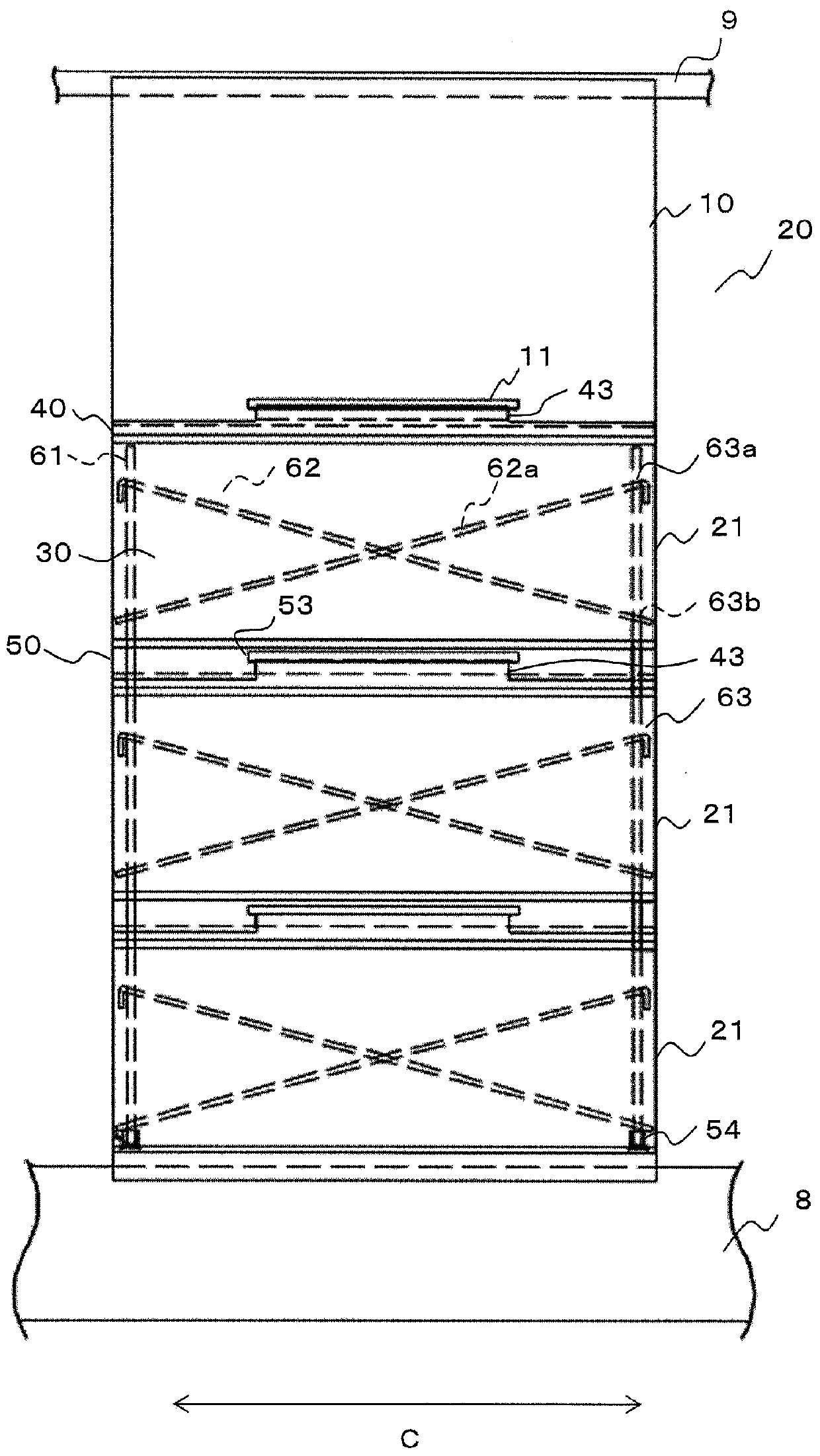
[0074] In the foregoing Embodiment 1, an example in which the second reinforcement 62 is fixed to the first reinforcement 61 by hooking the portion bent into a substantially V-shape at one end of the diagonal strut main body 62a to the upper mounting hole 63a was carried out. explained.
[0075] Therefore, when attaching the oblique strut main body 62 a in the first embodiment to the first reinforcement 61 , it is necessary to insert the unbent portion of the oblique strut main body 62 a from the outside of the panel 21 in the frontal width direction of the landing doorway 6 . The upper mounting hole 63a.
[0076] However, when inserting the diagonal support main body 62a from the outside of the panel 21 into the upper mounting hole 63a in the frontal width direction of the landing doorway 6, a space of approximately the same length as the panel 21 is required outside the panel 21. Therefore, in an elevator in which the hoistway 1 is small and there is no space necessary for ...
Embodiment approach 3
[0085] In the foregoing second embodiment, the main panel portion 30 is reinforced in the vertical direction between the panels 21 by the reinforcement member 60 . However, reinforcement in the horizontal direction, which is the connecting portion between the panels 21, has not been achieved. Therefore, in this Embodiment 3, the example which provided the inter-panel reinforcement 65 also in the connection part between the panels 21, and reinforced the connection part between the panels 21 is demonstrated.
[0086] Figure 7 It is a side view showing the elevator protective panel 20 according to Embodiment 3 of the present invention. also, Figure 8 is shown from Figure 7 The front view of the state in which the guard plate 20 is observed from the direction of arrow VIII.
[0087] Such as Figure 7 and Figure 8 As shown, the joint between the panels 21 is provided with an inter-panel stiffener 65 for reinforcing the joint. The inter-panel reinforcement 65 is arranged ...
PUM
 Abstract
Description
Claims
Application Information
 - R&D
- Intellectual Property
- Life Sciences
- Materials
- Tech Scout
- Unparalleled Data Quality
- Higher Quality Content
- 60% Fewer Hallucinations
Browse by: Latest US Patents, China's latest patents, Technical Efficacy Thesaurus, Application Domain, Technology Topic, Popular Technical Reports.
© 2025 PatSnap. All rights reserved.Legal|Privacy policy|Modern Slavery Act Transparency Statement|Sitemap|About US| Contact US: help@patsnap.com


