Wavelength selective switch with increased frequency separation to avoid crosstalk

A wavelength and wavelength dispersion technology, applied in the field of wavelength selective switches with increased frequency intervals to avoid crosstalk, can solve problems such as bad crosstalk

Active Publication Date: 2017-09-26
莫仕有限责任公司
View PDF2 Cites 3 Cited by
  • Summary
  • Abstract
  • Description
  • Claims
  • Application Information

AI Technical Summary

Problems solved by technology

Such wavelength selective switches may exhibit undesirable crosstalk between individual channels of different function switches

Method used


Image

  • Wavelength selective switch with increased frequency separation to avoid crosstalk
  • Wavelength selective switch with increased frequency separation to avoid crosstalk
  • Wavelength selective switch with increased frequency separation to avoid crosstalk

Examples


Embodiment Construction

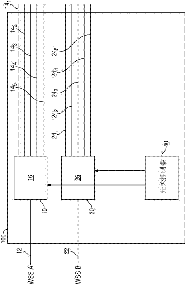
[0009] figure 1 is a functional block diagram of one example of a wavelength selective switch (WSS) 100, which in some cases may further include an integrated channel monitor. As shown, 3 different functions are shown in the figure: 2 1xnWSSs, denoted WSS 10 and WSS 20, and 1 Optical Channel Monitor 30 (OCM). However, it should be noted that, as described below, 3 different functions can be combined into a single physical switching device.

[0010] WSS 10 includes input port 12 and output port 14 1 、14 2 、14 3 、14 4 and 14 5 ("14"). Switch fabric 16 optically couples input port 12 to output port 14 such that an optical signal received at output port 12 can be selectively directed to one of output ports 14 under the control of switch controller 40 . Likewise, the WSS 20 includes an input port 22 and an output port 24 1 ,twenty four 2 ,twenty four 3 ,twenty four 4 and 24 5 ("twenty four"). Switch fabric 26 optically couples input port 22 to output port 24 such that ...


PUM


Abstract

An optical device incorporates into the same physical structure the functionality of two or more wavelength selective switches. The wavelength components associated with the first optical switch are isolated from the wavelength components associated with the second optical switch by their spatial displacement along one axis on a programmable optical phase modulator. Remaining crosstalk between the components is reduced by spatially separating the components of the two wavelength switches having the same wavelength along another axis of the programmable optical phase modulator.

Description

Background technique [0001] In an optical communication network, an optical signal with multiple optical channels on a single wavelength (channel) can usually be sent from one place to another through a single optical fiber. Optical cross-connect modules allow optical signals to be switched from one fiber to another. A wavelength-selective optical cross-connect or wavelength-selective switch (WSS) allows reconfiguration of wavelength-dependent switching, that is, allows switching of certain wavelength channels from a first fiber to a second fiber while leaving other wavelength channels in the first fiber transmission, or to allow switching of certain wavelength channels to a third fiber. The optical network architecture based on wavelength selective optical switching has many attractive features due to the automatic creation of single-wavelength channel optical paths or rerouting. It can accelerate service deployment, accelerate rerouting around optical network failure point...

Claims


Application Information

Patent Timeline
Patent Type & Authority Applications(China)
IPC IPC(8): G02B6/35
CPCG02B6/354H04Q2011/0049H04Q2011/0016H04Q2011/0024H04Q11/0005H04Q2011/0026H04J14/0212H04Q2011/0035H04Q2011/0007H04Q2011/003
Inventor J·L·瓦格纳
Owner 莫仕有限责任公司
Why Eureka
Try Eureka