Optical transmission device and optical signal gain control method

a technology of optical transmission device and optical signal, which is applied in the direction of electromagnetic transceivers, multi-channel communication, wavelength-division multiplex systems, etc., can solve the problems of large overshoot and undershoot, danger of damaging a transmission apparatus including the optical transmission device, and the inability to correctly monitor the gain of the devi

Active Publication Date: 2019-04-18
FUJITSU LTD
View PDF3 Cites 2 Cited by
  • Summary
  • Abstract
  • Description
  • Claims
  • Application Information

AI Technical Summary

Problems solved by technology

Under such a state, in a case where the number of wavelengths varies, if the respective optical transmission devices 1100, 1111, and 1112 perform the control of stabilizing the output power simultaneously, large overshoot and undershoot occur, and there is a danger of damaging a transmission apparatus including the optical transmission device 1112.
However, in a case of the device gain steady control, only the total power of the input and output of the optical transmission device 1100 may not be detected by the PD as described above, and thus, the device gain may not be correctly monitored, and the gain steady control may not be performed with high accuracy.
As described above, in a case where the optical transmission device is connected to the optical transmission devices of other companies, the respective optical transmission devices may not correctly monitor a gain between an input and an output, and, despite the fact that an actual gain does not reach a target gain, it is erroneously recognized that the actual gain reaches the target gain.
In a WDM transmission system in which the optical transmission devices are connected in multiple stages on a transmission path, power deviation in each optical transmission device accumulates, which causes a problem of deterioration in signal quality.

Method used


Image

  • Optical transmission device and optical signal gain control method
  • Optical transmission device and optical signal gain control method
  • Optical transmission device and optical signal gain control method

Examples


embodiments

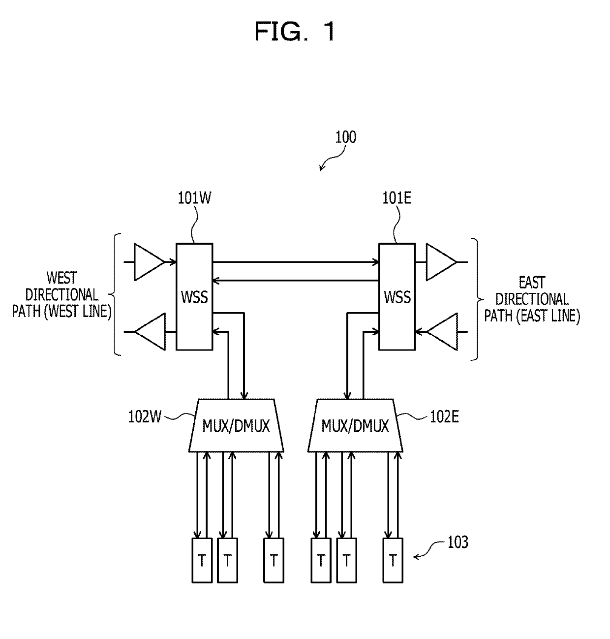
[0032]FIG. 1 is a diagram illustrating a configuration example of an optical transmission device. An optical transmission device 100 illustrated in FIG. 1 is a configuration example of a ROADM, and respective WDM signals from different directional paths (WEST directional path and EAST directional path) are input.

[0033]The ROADM 100 includes wavelength selective switches (WSS) 101W and 101E, multiplexer (MUX) / demultiplexer (DMUX) 102W and 102 E, and a plurality of transponders (T) 103. The wavelength selective switch 101W processes the WDM signal input from the WEST directional path and the WDM signal output to the WEST directional path. In the same manner, the wavelength selective switch 101E processes the WDM signal input from the EAST directional path and the WDM signal output to the EAST directional path.

[0034]The wavelength selective switches 101W and 101E are connected to each other to form a through (THRU) path of the optical signal. The wavelength selective switch 101W includ...


PUM


Abstract

An optical transmission device includes an optical amplifier that optically amplifies a wavelength multiplexing signal which is input, a wavelength selective switch that splits, inserts, or transmits an optical signal of any wavelength of the wavelength multiplexing signal, an optical channel power monitor that detects power of each channel of the wavelength multiplexing signal which is input and the wavelength multiplexing signal which is output, and a controller that calculates an amount of change in the optical signal of each channel in which a gain of each channel between an input and an output to and from the device is steady, and adjusts an amount of attenuation of the wavelength selective switch, based on the power of each channel of the wavelength multiplexing signal that is detected by the optical channel power monitor.

Description

CROSS-REFERENCE TO RELATED APPLICATION[0001]This application is based upon and claims the benefit of priority of the prior Japanese Patent Application No. 2017-200306, filed on Oct. 16, 2017, the entire contents of which are incorporated herein by reference.FIELD[0002]The embodiments discussed herein are related to an optical transmission device and an optical signal gain control method that control a gain of a wavelength division multiplexing optical signal and transmit the controlled signal.BACKGROUND[0003]In order to realize a high-capacity optical communication, multiplexing of optical signals performed by wavelength division multiplexing (WDM) is widespread. In the WDM transmission system, a WDM signal in which a plurality of wavelength channels are multiplexed is transmitted. A reconfigurable optical add drop multiplexer (ROADM) is provided in each node of the WDM transmission system as an optical transmission device. The ROADM may split an optical signal of a desirable wavele...

Claims


Application Information

Patent Timeline
Patent Type & Authority Applications(United States)
IPC IPC(8): H04B10/079H04J14/02
CPCH04B10/07955H04B10/07957H04J14/0221H04J14/0212H04B10/40H04J14/02H04J14/0201H04B10/60H04B10/50
Inventor YUKI, MASAHIRO
Owner FUJITSU LTD
Why Eureka
Try Eureka