
Wavelength selective switch and reconfigurable optical add/drop multiplexer

Active Publication Date: 2019-10-24
XIEON NETWORKS SARL
View PDF15 Cites 2 Cited by
  • Summary
  • Abstract
  • Description
  • Claims
  • Application Information

AI Technical Summary

Benefits of technology

The present invention is a dual input wave group wavelength selective switch that can be used in a reconfigurable optical add / drop multiplexer (ROADM) structure. This switch offers colorless, directionless, and hitless switching, which improves the efficiency of the switch and reduces the amount of cabling required between various modules. A configuration shown in FIGS. 12a, 12b allows for an efficient broadcast and select ROADM with colorless and directionless add / drop capability, while still relying to a large extent on conventional and low-cost components. This invention provides a cost-efficient implementation of a ROADM structure.

Problems solved by technology

This limitation can be caused by the wavelength contention of WSS used within the add / drop port group.
With an increasing nodal degree, the add / drop capacity is expected to grow, but in reality decreases because of the limited number of WSS ports available.
This places challenges on the ability to build ROADM structures with a high number of input and output ports, in particular in dense wavelength division multiplexing (DWDM) scenarios in which independent routing of at least two channel sets with spectral overlap through a WSS with a large port count (e.g. 8 ports or higher) is required.
However, these techniques require a sophisticated control of the optical elements, which provides challenges in real-life applications.
If the images are not properly maintained, undesired passband effects can occur.
However this limits the port count and the general useability of the WSS, because low and high order unwanted beams are hitting ports depending on the switch configuration.

Method used


Image

  • Wavelength selective switch and reconfigurable optical add/drop multiplexer
  • Wavelength selective switch and reconfigurable optical add/drop multiplexer
  • Wavelength selective switch and reconfigurable optical add/drop multiplexer

Examples


Embodiment Construction

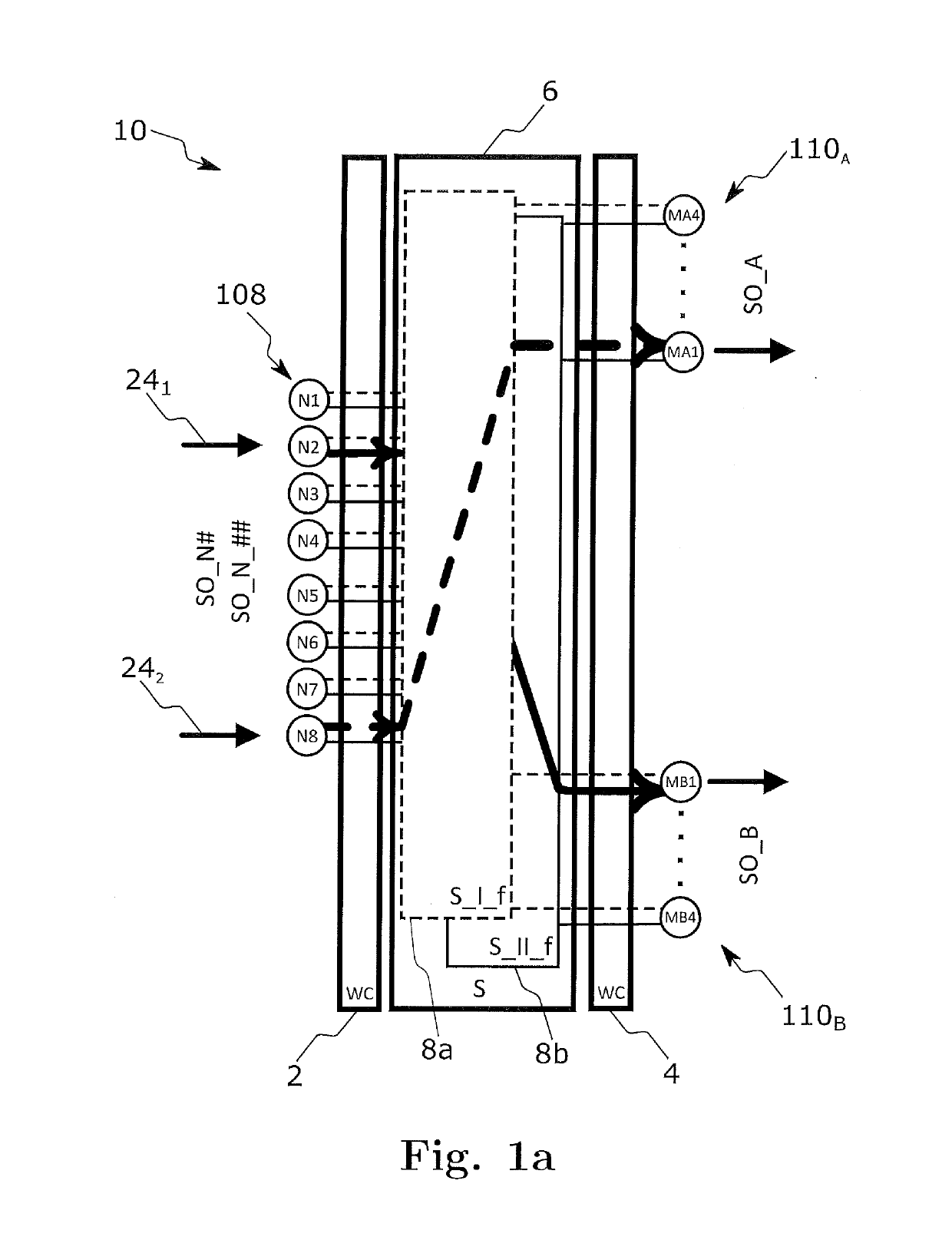
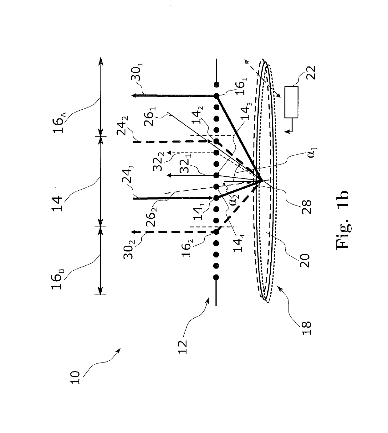
[0106]FIG. 1a is a schematic illustration of a wavelength selective switch (WSS) 10 according to an embodiment. The WSS 10 is an optical N×(MA & MB) switch that can independently switch individual wavelength channels from a first set of N input ports to a second and a third set of MA and MB output ports, wherein N≥2, MA≥1 and MB≥1. In the configuration of FIG. 1a, eight input ports 108 N1 to N8 are shown and switched to a second set of four output ports 110A MA1 to MA4 and a third set of four output ports 110B MB1 to MB4. However, these numbers are mere examples, and a wavelength selective switch according to an embodiment may comprise a smaller or larger number of input ports, and a smaller or larger number of output ports, as desired.

[0107]As can be taken from FIG. 1a, the second set 110A of MA output ports and the third set 110E of MB output ports each is capable to receive, distributed over its of output ports, a DWDM signal SOA and SOB, respectively. Each of these two DWDM sign...


PUM


Abstract

A wavelength selective switching device comprises a plurality of input paths for receiving optical signals, a plurality of output paths for emitting the optical signals, and a switching unit for selectively directing the optical signals from the input paths to the output paths. The switching unit comprises a reflective area adapted to be concurrently illuminated by a first optical signal from a first input path among the plurality of input paths, and by a second optical signal from a second input path among the plurality of input paths, the second input path being different from the first input path, and to concurrently direct the first optical signal to a first output path among the plurality of output paths and the second optical signal to a second output path among the plurality of output paths, the second output path being different from the first output path. Said first output path and said second output path are spatially separated by said first input path and said second input path, or vice-versa.

Description

FIELD OF THE INVENTION[0001]The invention relates to a wavelength selective switch (WSS) and a reconfigurable optical Add / Drop Multiplexer (ROADM), in particular for independent routing and optically attenuating of at least two optical channel sets with spectral overlap.BACKGROUND[0002]In a wavelength division multiplexed (WDM) optical network, optical signals encoded with streams of information are multiplexed to form a WDM signal. The WDM signal is transmitted through a series of optical fibers. At the egress point the optical signal are demultiplexed. The streams of information are retrieved by means of optical receivers.[0003]Wavelength selective switches (WSS) may be employed in the optical transmission path to selectively receive optical signals from among a first plurality of optical fibers and to selectively transmit optical signals via a second plurality of optical fibers. Contentionfree routing of two channels in the same optical frequency band may require to cross connect...

Claims


Application Information

Patent Timeline
IPC IPC(8): H04J14/02H04Q11/00G02B6/35G02B6/293
CPCG02B6/29305H04Q2011/0016H04J14/0212H04Q11/0005G02B6/29382G02B6/3512G02B6/356G02B6/29395G02B6/2793G02B6/2931H04J14/02122
Inventor SCHIMPE, ROBERT
Owner XIEON NETWORKS SARL
Learn More