Adjustable space walker

A spacewalking machine and a technology for installing a cavity, which is applied in the field of sports equipment, can solve the problems of not being able to effectively adjust the exercise intensity and cannot meet the needs of different groups of people for exercise intensity, and achieve the effect of simple structure, simple structure, and stable structure

Inactive Publication Date: 2017-09-29
HEFEI KANGZHIHENG MACHINERY TECH CO LTD
View PDF7 Cites 6 Cited by
  • Summary
  • Abstract
  • Description
  • Claims
  • Application Information

AI Technical Summary

Problems solved by technology

[0005] But the above-mentioned space walk machine cannot effectively adjust the exercise intensity, and cannot meet the needs of different groups of people for exercise intensity, so an adjustable space walk machine is needed to solve the above problems

Method used


Image

  • Adjustable space walker
  • Adjustable space walker
  • Adjustable space walker

Examples


Embodiment 1

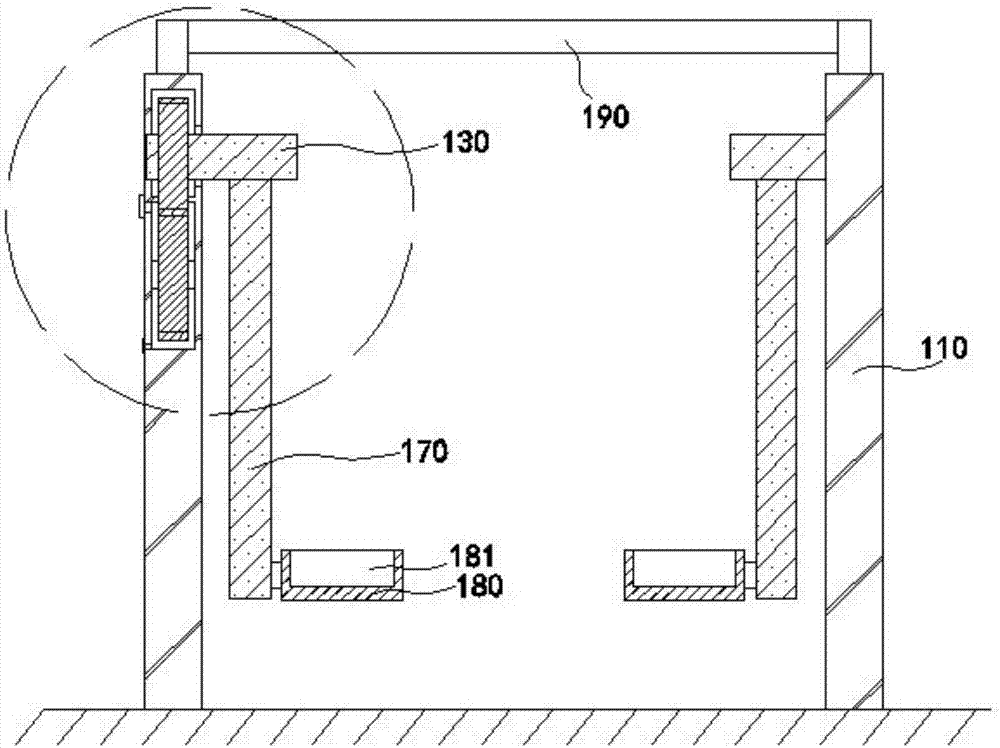
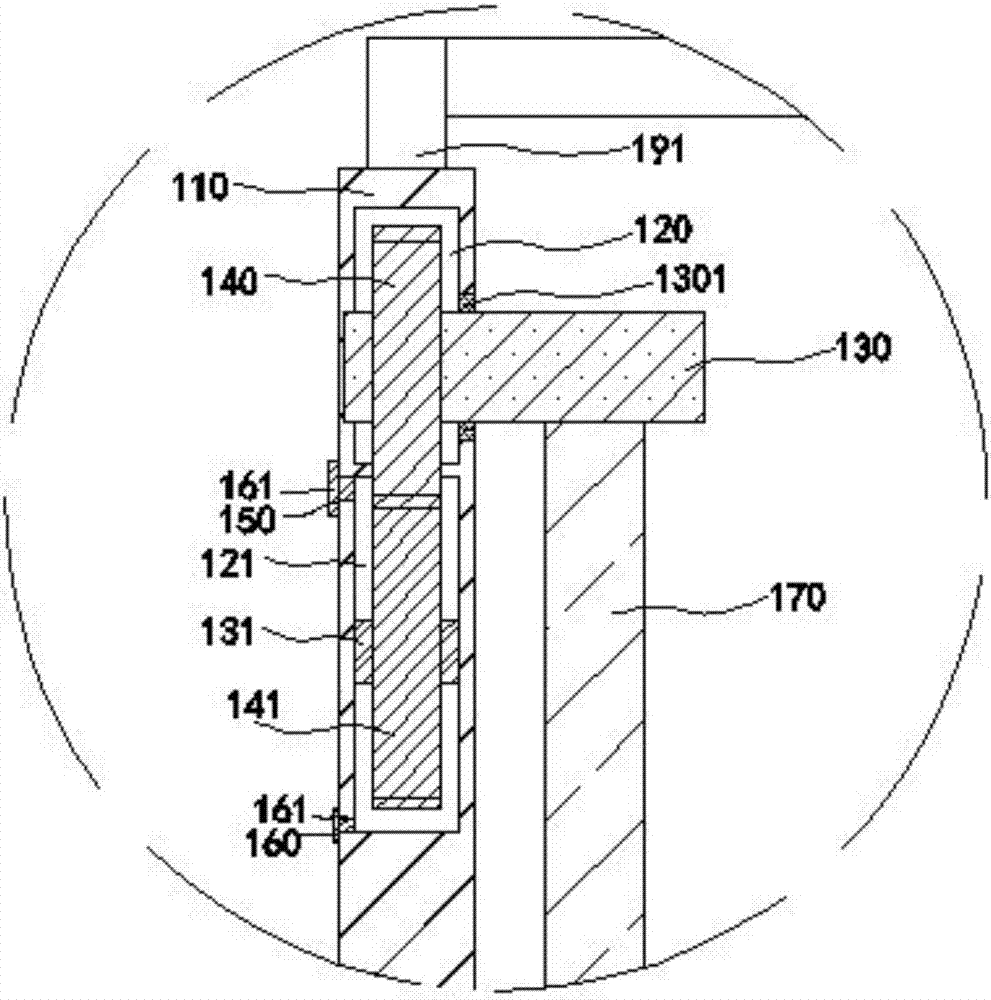
[0033] Such as figure 1 , figure 2 and image 3 Shown is an adjustable space walking machine of this embodiment, which includes two vertical poles 110 standing on the ground, and the top of any vertical pole 110 is provided with a closed first installation cavity 120, and one end of the first rotating pole 130 is Rotationally connected to the side wall of the first installation chamber 120, the other end of the first rotating rod 130 passes through the first installation chamber 120 and is connected with a movable rod 170 perpendicular to the first rotating rod 130, and the bottom end of the connecting rod 170 is provided with a foot Pedal 180; a first gear 140 is fixedly sleeved on the first rotating rod 130, and the first gear 140 is located in the first installation cavity 120;

[0034] Below the first installation cavity 120 is provided a closed second installation cavity 121 for storing water, the first gear 140 penetrates into the second installation cavity 121 and me...

Embodiment 2

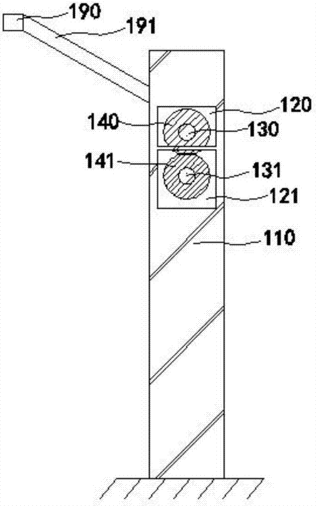
[0050] Such as figure 2 , image 3 and Figure 4 Shown is an adjustable space walking machine of this embodiment, which includes two vertical poles 110 standing on the ground, and the top of any vertical pole 110 is provided with a closed first installation cavity 120, and one end of the first rotating pole 130 is Rotationally connected to the side wall of the first installation chamber 120, the other end of the first rotating rod 130 passes through the first installation chamber 120 and is connected with a movable rod 170 perpendicular to the first rotating rod 130, and the bottom end of the connecting rod 170 is provided with a foot Pedal 180; a first gear 140 is fixedly sleeved on the first rotating rod 130, and the first gear 140 is located in the first installation cavity 120;

[0051] Below the first installation cavity 120 is provided a closed second installation cavity 121 for storing water, the first gear 140 penetrates into the second installation cavity 121 and m...


PUM


Abstract

The invention discloses an adjustable space walker and relates to the technical field of sports equipment; the adjustable space walker comprises two vertical bars; the top end of each vertical bar is provided with a first mounting cavity, one end of a first rotary bar is rotationally connected to the sidewall of the first mounting cavity, the other end of the first rotary bar is passed through the first mounting cavity and connected with a moving bar, the bottom end of a connection bar is provided with a footboard, a first gear fixedly sleeves the first rotary bar and is positioned in the first mounting cavity, a second cavity is arranged below the first mounting cavity, the first gear is passed through the second mounting cavity and meshed with a second gear, the second gear fixedly sleeves a second rotary bar, two ends of the second rotary bar are rotationally connected to two cavity walls of the second mounting cavity, the second mounting cavity is provided with a water injection hole and a water outlet, and each of the water injection hole and the water outlet is provided with a plug; one side of each vertical bar is provided with the corresponding connection bar, and a handlebar is connected to the heads of the two connection bars. The adjustable spacer walker allows exercise intensity to be adjusted through resistance of water.

Description

technical field [0001] The invention belongs to the technical field of sports equipment, and in particular relates to an adjustable space walker. Background technique [0002] Sports equipment is the general term for the various apparatuses, equipment and articles for use in competitive sports competitions and body-building exercises. Sports equipment and sports are interdependent and promote each other. The popularization of sports and the diversification of sports make the types and specifications of sports equipment develop. Equally, the sports equipment superior in quality, performance is stable, safe and reliable can not only guarantee athletic competition to be carried out just and under the situation of fierceness, but also to promote the raising of sports level to create necessary material conditions. The human body is an organic whole composed of various organ systems. When performing physical activities, it seems that only the muscles are active. In fact, the brea...

Claims


Application Information

Patent Timeline
Patent Type & Authority Applications(China)
IPC IPC(8): A63B22/04A63B21/008
CPCA63B21/008A63B22/04
Inventor 廖月
Owner HEFEI KANGZHIHENG MACHINERY TECH CO LTD
Why Eureka
Try Eureka