Carbon ion source device with reflector power supply

A technology of reflector and source device, which is applied in the direction of circuits, discharge tubes, electrical components, etc., can solve the problems of product yield loss, time-consuming, and arc-starting chamber adjustment, so as to improve the quality of injection and product quality. efficiency, pollution reduction effect

Pending Publication Date: 2022-04-15
北京凯世通半导体有限公司
View PDF0 Cites 0 Cited by
  • Summary
  • Abstract
  • Description
  • Claims
  • Application Information

AI Technical Summary

Problems solved by technology

The carbon accumulated on the surface of the side wall of the arc chamber will reduce the plasma dissociation efficiency and the ion beam current will become smaller; while the carbon accumulated at the extraction slot will form burrs, which will block the passage of part of the ion beam and cause the ion beam to flow The overall uniformity is reduced, and the difficulty of beam forming is increased
In addition, when the carbon accumulates to a certain extent, it will peel off, and the peeled carbon has a certain probability to reach the process chamber with the ion beam and adsorb on the surface of the wafer, thus causing damage to the product yield.
Furthermore, the electrons moving in the arcing chamber will hit the arcing chamber and the cover plate to generate metal ions, which will cause pollution to the generated ion beam and the analysis magnet.
And, at present, the potential of the cathode and the reflector in the arcing chamber is the same, and the electric field strength in the arcing chamber cannot be adjusted intuitively and conveniently, resulting in poor electron movement distance or speed, which affects the effect of plasma generation; or it takes more time to debug Multiple power supplies with low efficiency cannot meet the production needs of large-scale production lines

Method used


Image

  • Carbon ion source device with reflector power supply
  • Carbon ion source device with reflector power supply
  • Carbon ion source device with reflector power supply

Examples


Embodiment Construction

[0022] The technical solutions in the patent embodiments of the present invention will be clearly and completely described below in conjunction with the accompanying drawings in the patent embodiments of the present invention. Obviously, the described embodiments are only a part of the patent embodiments of the present invention, not all of them. Example. Based on the embodiments in the patent of the present invention, all other embodiments obtained by persons of ordinary skill in the art without making creative efforts belong to the protection scope of the patent of the present invention.

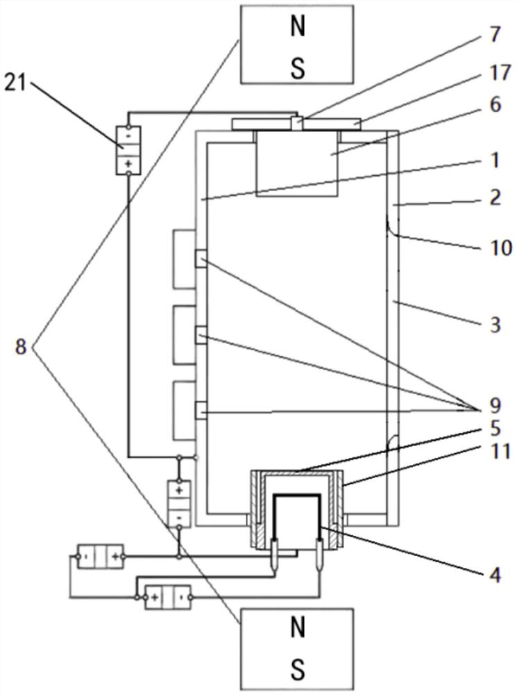
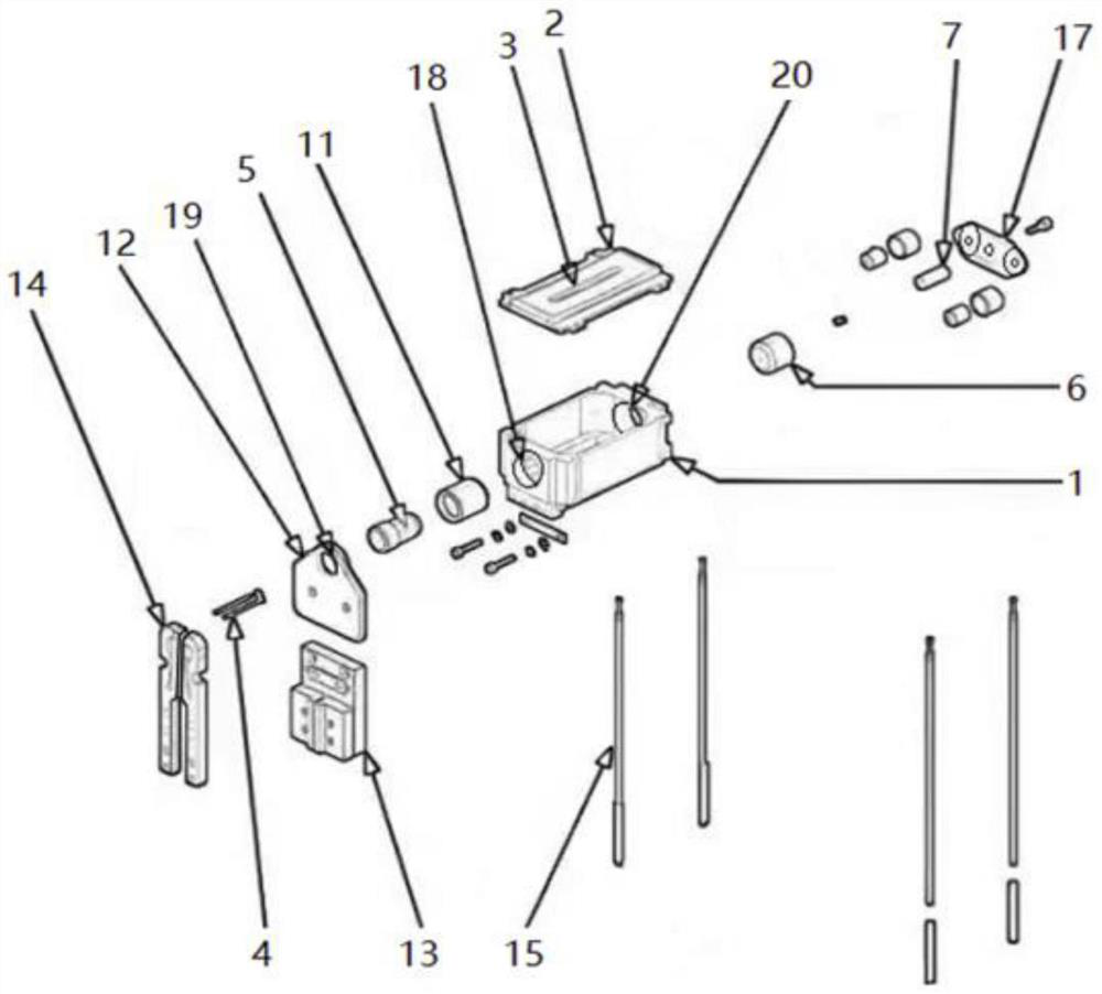
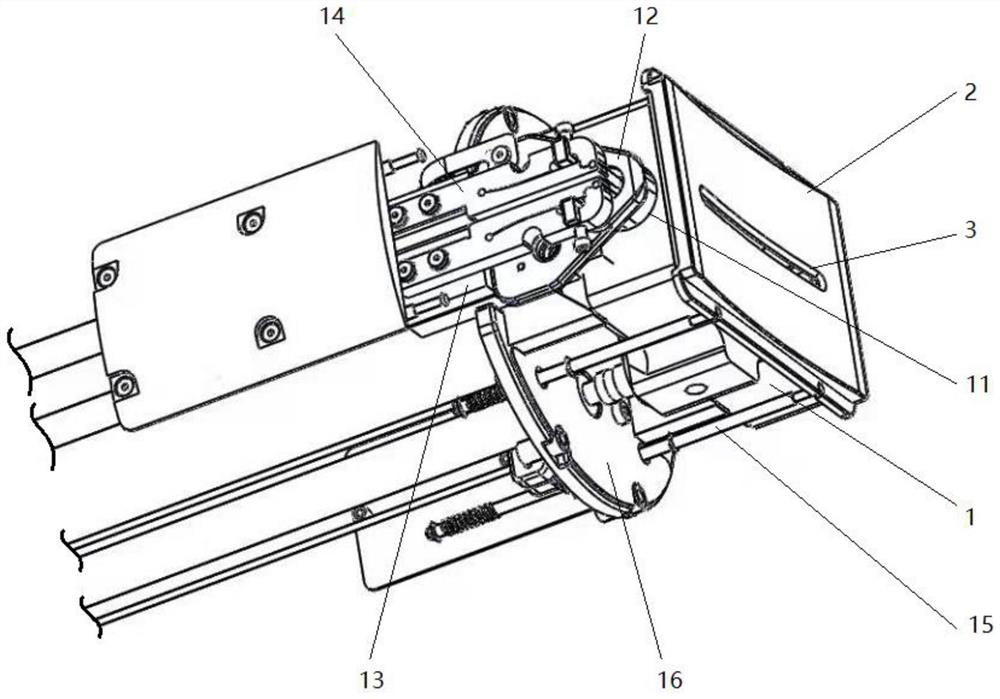
[0023] The present invention provides an ion source device for a carbon ion implantation process, wherein the ion source for a carbon ion implantation process is a device that ionizes neutral atoms or molecules and generates carbon plasma; the ion source device of the present invention It can reduce the accumulation of carbon and the pollution of impurity ions, and it is convenient to adju...


PUM


Abstract

The invention relates to a carbon ion source device with a reflector power supply. The carbon ion source device with the reflector power supply comprises an arc chamber, a cover plate, a lamp filament, a cathode, a reflector and a vent hole, the arcing chamber is used as a chamber for generating plasmas by collision of electrons and gas molecules; the cover plate is provided with a leading-out slit used for leading out plasma, and the plasma is led out of the arcing chamber. The filament generates a first group of electrons after being heated, and the first group of electrons are used for heating the cathode; after the cathode is heated, a second group of electrons is generated, and the second group of electrons is used for arcing; the reflecting electrode is arranged on one side, opposite to the cathode, in the arcing chamber and is used for constructing an electric field in the arcing chamber; and the vent hole is formed in the inner wall of the arcing chamber and is used for inputting gas into the arcing chamber. The ion source device provided by the invention can obtain a larger and purer carbon ion beam, the electric field intensity is convenient to adjust, the injection quality is improved, and the product yield is improved.

Description

technical field [0001] The invention belongs to the field of semiconductor manufacturing and processing, and relates to a carbon ion source device with a reflector power supply, which is suitable for ion implantation equipment. Background technique [0002] Ion implantation technology is a very important doping method in the field of semiconductor chip manufacturing. Carbon, as an effective means of combined ion implantation, is used to create ultra-shallow junctions and abrupt junctions, and to inhibit the diffusion of dopant atoms such as boron. [0003] In the process of ion implantation, it is not only necessary to precisely control parameters such as implant energy, dose, and angle, but also to strictly control the contamination during implantation. Once the pollution increases, the equipment must be cleaned and maintained, which greatly reduces the effective running time of the equipment and increases the operating cost of the machine. However, due to its own characte...

Claims


Application Information

Patent Timeline
Patent Type & Authority Applications(China)
IPC IPC(8): H01J37/08H01J37/317
Inventor 洪俊华刘金涛郑皓文侯爽李轩王雨淋王振辉雷晓刚关天祺孙世豪
Owner 北京凯世通半导体有限公司
Why Eureka
Try Eureka