A textile winding mechanism

A technology of winding mechanism and winding frame, which is applied in the direction of conveying filamentous materials, thin material processing, transportation and packaging, etc. It can solve the problems of difficulty in improving winding efficiency, cumbersome winding steps, and affecting winding speed, etc. , to achieve the effect of preventing uneven winding, improving running stability and winding speed

Active Publication Date: 2018-03-27
河北澜浩羊绒制品有限公司
View PDF9 Cites 0 Cited by
  • Summary
  • Abstract
  • Description
  • Claims
  • Application Information

AI Technical Summary

Problems solved by technology

If the position of the wire is adjusted while winding the wire, although the occurrence of the winding phenomenon can be avoided, the speed of the winding is greatly affected. In addition, although the current automatic winding device can realize automatic wire distribution, the structure is complicated. The price is expensive, and the steps of replacing the bobbin after winding are cumbersome, which is not conducive to mass production in processing plants
Therefore, the efficiency of winding is always difficult to improve, and also reduces work efficiency

Method used


Image

  • A textile winding mechanism
  • A textile winding mechanism
  • A textile winding mechanism

Examples


Embodiment Construction

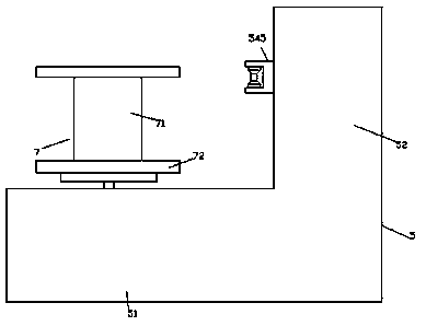
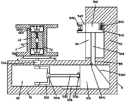
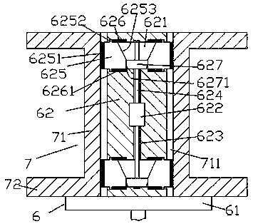
[0020] Such as Figure 1-Figure 5 As shown, a textile winding mechanism of the present invention includes a winding frame body 5 composed of a first frame body 51 and a second frame body 52, and the first frame body 51 is provided with a cavity extending left and right 53, the inner front wall on the right side of the cavity 53 is provided with a first sliding groove 535, and the first sliding groove 535 is provided with a sliding block 531 whose rear side extends into the cavity 53 and is slidably connected. A hinge 5311 is provided on the left end surface of the sliding block 531 in the cavity 53, and a hinged push rod 532 extending to the left is hinged in the hinge 5311, and the left end of the hinged push rod 532 is A hinged sleeve 5331 is provided, and a U-shaped hinged rod 533 is set inside the hinged sleeve 5331. The front end of the U-shaped hinged rod 533 is rotatably connected with the front inner wall of the cavity 53, and the U-shaped hinged rod The rear side end...


PUM


Abstract

The invention discloses a convenient and rapid type textile winding mechanism which comprises a winding frame body composed of a first frame main body and a second frame main body. The first frame main body is internally provided with a cavity arranged in a left-right extension mode; a first sliding groove is formed in the inner front wall of the right side of the cavity; a sliding block is arranged in the first sliding groove, wherein the rear side of the sliding block extends into the cavity, and the sliding block is slidably connected with the first sliding groove in a matched mode; a hinging piece is arranged on the end face of the left side of the sliding block in the cavity; a hinging pushing rod extending towards the left side is hinged into the hinging piece; a hinging sleeve is arranged at the tail end of the left side of the hinging pushing rod; a U-shaped hinging rod is sleeved with the hinging sleeve; the front side end of the U-shaped hinging rod is rotatably connected with the inner wall of the front side of the cavity in a matched mode; the rear side end of the U-shaped hinging rod is connected with a winding motor in a matched mode; the outer surface of the winding motor is embedded in the inner wall of the rear side of the cavity and is fixedly connected with the inner wall of the rear side of the cavity; a second sliding groove arranged in a front-rear extension mode is formed in the end face of the left side of the second frame main body; and a moving block is arranged in the second frame main body. The structure is simple, quick mounting and dismounting can be realized, the replacing speed of a thread cylinder is increased, and winding work can be evened.

Description

technical field [0001] The invention relates to the technical field of textile machinery and equipment, in particular to a textile winding mechanism. Background technique [0002] The winding device is an indispensable tool in the textile field. However, the winding devices on the market drive the winding by rotating the reel when winding. Generally, a single person is used to operate the winding, and the winding due to uneven distribution of the wires often occurs, and the chuck or the center of gravity is biased to one side so that the wires fall out of the disk. For this reason, the staff had to stop and arrange the lines, which was a waste of time. If the position of the wire is adjusted while winding the wire, although the occurrence of the winding phenomenon can be avoided, the speed of the winding is greatly affected. In addition, although the current automatic winding device can realize automatic wire distribution, the structure is complicated. The price is expens...

Claims


Application Information

Patent Timeline
Patent Type & Authority Patents(China)
IPC IPC(8): B65H54/28B65H57/14B65H54/54B65H54/44
CPCB65H54/2818B65H54/44B65H54/543B65H57/14B65H2701/31
Inventor 詹贺钫
Owner 河北澜浩羊绒制品有限公司
Why Eureka
Try Eureka