a water conservancy device

A water conservancy and slip groove technology, applied in the direction of hoisting device, clockwork mechanism, etc., can solve the problems of troublesome well rope disassembly and assembly, easy aging and fracture of well rope, low degree of automation, etc., and achieve uniform well rope winding. Work, improve operational stability and well rope winding speed, the effect of low maintenance cost

Active Publication Date: 2018-10-16
WENLING QIHAO ELECTRONICS CO LTD
View PDF7 Cites 0 Cited by
  • Summary
  • Abstract
  • Description
  • Claims
  • Application Information

AI Technical Summary

Problems solved by technology

In order to draw water safely and conveniently, a potter's wheel will be set up next to the well, but the potter's wheel needs to be rolled by hand to retract the well rope, which has a low degree of automation, and the well rope is easily distributed unevenly when it is wrapped around the head of the potter's wheel, which affects normal use. The well rope is blown by the wind. The rain is easy to age and break, so it needs to be replaced in time. The disassembly and assembly of the traditional potter's wheel well rope is very troublesome and dangerous

Method used


Image

  • a water conservancy device
  • a water conservancy device
  • a water conservancy device

Examples


Embodiment Construction

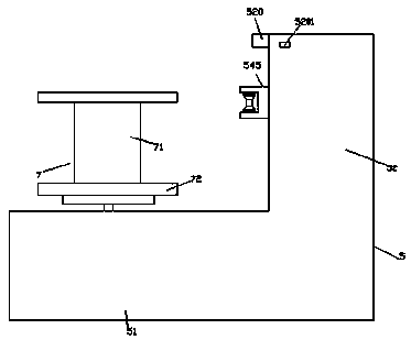
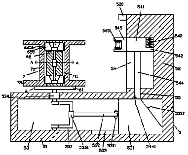
[0022] Such as Figure 1-Figure 6 As shown, a kind of water conservancy device of the present invention comprises the well rope winding frame 5 that is fixedly installed on the water well edge that is made up of first frame 51 and second frame 52, and described first frame 51 is equipped with There is a hollow cavity 53 extending left and right, the right side of the hollow cavity 53 is provided with a first sliding groove 535, and a sliding block 531 is provided in the first sliding groove 535, and the sliding block 531 is arranged in the hollow cavity. A flexible connection part 5311 is provided on the left side of the sliding block 531 in the 53, and a pushing rod 532 extending to the left is flexibly connected in the flexible connecting part 5311, and the left tail of the pushing rod 532 is provided with a fixed Sleeve 5331, the solid sleeve 5331 is provided with a half-ring rod 533, the front side of the half-ring rod 533 is connected with the inner wall of the front side...


PUM


Abstract

The invention discloses a water conservancy device. The water conservancy device comprises a well rope winding rack; the well rope winding rack comprises a first rack and a second rack and is fixedly mounted beside a well; a hollow cavity extending leftwards and rightwards is formed in the first rack; a first sliding groove is formed in the right side of the hollow cavity; a sliding block connected in a sliding fit manner is arranged in the first sliding groove; a flexible connecting part is arranged on the left side surface of the sliding block in the hollow cavity; a push rod extending to the left side is flexibly connected in the flexible connecting part; a fixed sleeve is arranged at the tail of the left side of the push rod; a semi-circular rod piece is arranged in the fixed sleeve; the front side of the semi-circular rod piece is connected with the inner wall of the front side of the hollow cavity in a rotary fit manner; the back side of the semi-circular rod piece is connected with a well rope winding motor in a fit manner; the well rope winding motor is arranged in the inner wall of the back side of the hollow cavity and is fixedly connected with the inner wall; a second sliding groove extending forwards and backwards is formed in the left side surface of the second rack; and a second sliding block is arranged in the second sliding groove. The water conservancy device is simple in structure and can be mounted and dismounted quickly, the bobbin change speed can be increased, and the well rope winding work can be even.

Description

technical field [0001] The invention relates to the technical field of water conservancy equipment, in particular to a water conservancy device. Background technique [0002] In areas with abundant groundwater, people will dig wells to extract groundwater for irrigation or living. In order to draw water safely and conveniently, a potter's wheel will be set up next to the well, but the potter's wheel needs to be rolled by hand to retract the well rope, which has a low degree of automation, and the well rope is easily distributed unevenly when it is wrapped around the head of the potter's wheel, which affects normal use. The well rope is blown by the wind. It is easy to age and break due to rain, so it needs to be replaced in time. The disassembly and assembly of the traditional pulley well rope is very troublesome and dangerous. Contents of the invention [0003] The technical problem to be solved by the present invention is to provide a water conservancy device, which can...

Claims


Application Information

Patent Timeline
Patent Type & Authority Patents(China)
IPC IPC(8): B66D1/12B66D1/36B66D1/28
CPCB66D1/12B66D1/28B66D1/36
Inventor 杨丽君
Owner WENLING QIHAO ELECTRONICS CO LTD
Why Eureka
Try Eureka