

Fluidic kinetic energy generating set
A generator set and kinetic energy technology, applied in wind power generation, wind power motor combination, renewable energy power generation, etc., can solve the problems that generator sets are difficult to maintain normal operation, generator sets are not equipped with protection devices, and damage that cannot be recovered, etc., to achieve The effect of compact structure, low manufacturing cost and strong environmental adaptability
- Summary
- Abstract
- Description
- Claims
- Application Information
AI Technical Summary
Problems solved by technology
Method used
Image

Examples
Embodiment 1
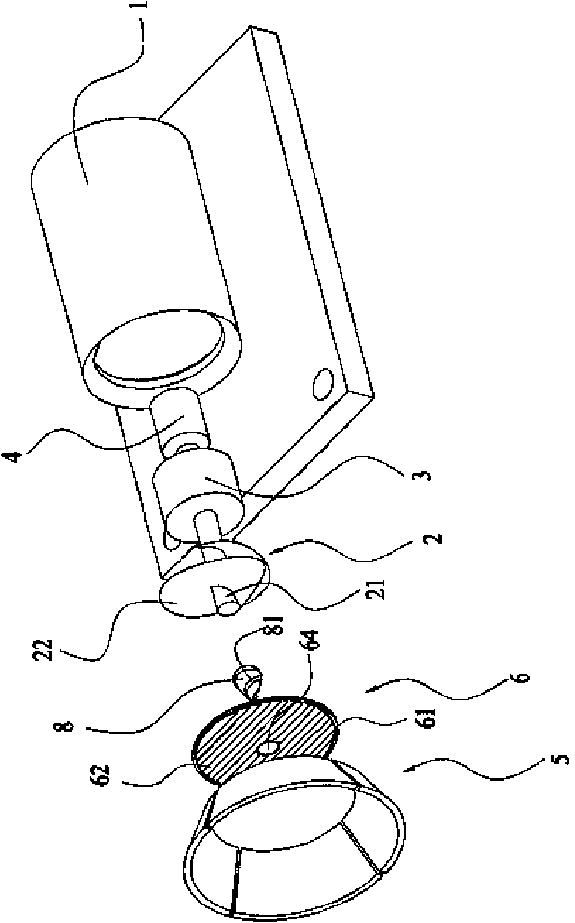
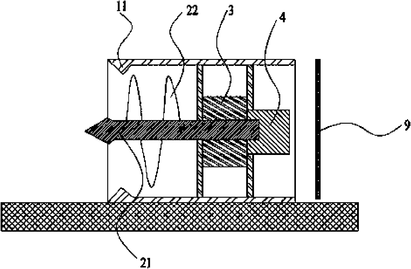
[0029] Such as figure 1 As shown in , a hydrokinetic generator set includes a casing 1 , an impeller 2 installed inside the casing 1 , a transmission 3 and a generator 4 .
[0030] The impeller 2 includes a central shaft 21 and a blade 22 with a helical surface wound around the central shaft. The impeller central shaft 21 is fixedly connected to the rotor shaft of the generator 4 at a distance from the crankshaft of the transmission 3 .
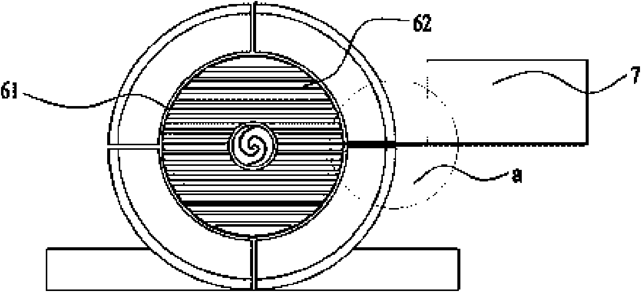
[0031] The inlet end of the casing 1 is fixedly connected to the outer peripheral edge of the bottom of a trumpet-shaped collecting cover 5, and the pressure controlling collecting cover 5 is composed of 4 arc-shaped blocks separated by a certain gap. The inner peripheral edge of the bottom of the pressure control collecting cover 5 is connected with a louver 6. The louver includes a frame 61, several blades 62 arranged in parallel, a blade shaft 63 and a pull rod. The two sides of the upper end of the blade 62 are respectively provided with...
Embodiment 2
[0039] Such as Figure 5 As shown in , the difference between embodiment 2 and embodiment 1 is that a wind force suspension plate 7' is arranged on the side of the shutter 6, and the lower edge of the wind force suspension plate 7' is fixedly connected to the rotating shaft 63 of a blade 6 through a connecting rod 71. Under the action of gravity, the wind suspension plate 7' is in a vertically downward suspension state in a static state. At this time, the shutters are opened, and after the wind suspension plate 7' senses the change in the magnitude and direction of the wind flow, it can follow the wind flow The direction is rotated at a certain angle. Since the wind suspension plate 7' is linked with the louver blade 62, when the direction of the wind suspension plate 7' changes, the direction of the louver blade 62 can also be changed accordingly, so as to achieve the purpose of controlling the opening / closing of the protective net shutter. The purpose of automatic control is...
PUM
 Abstract
Description
Claims
Application Information