ball screw

A technology of ball screw and ball, which is applied in the field of ball screw, can solve the problems of labor cost, high cost, high manufacturing cost, etc., and achieve the effect of saving space

Active Publication Date: 2022-05-17
NIPPON THOMPSON +1
View PDF15 Cites 0 Cited by
  • Summary
  • Abstract
  • Description
  • Claims
  • Application Information

AI Technical Summary

Problems solved by technology

Since the oleoresin material is formed by mixing the resin material and lubricating oil in advance, and then injecting the mixed material, when the capacity of the lubricating oil decreases, the lubricating oil cannot be replenished, which easily leads to poor lubricity. In addition, the oil-impregnated resin material needs to be injection-molded integrally with the nut, so there is a problem that it takes time and effort to increase the manufacturing cost.
In addition, the rolling guide assembly achieves lubrication-free maintenance by having an oil supply part in the direction changing path of the end cover of the ball spline and an oil-containing part in the outer cylinder. However, the oil-containing part is assembled in the In the assembly hole, there are problems of complex structure and high cost

Method used


Image

  • ball screw
  • ball screw
  • ball screw

Examples


Embodiment Construction

[0069] The ball screw of the present invention is preferably applied to various equipment such as mechatronic products such as precision positioning tables and detection devices.

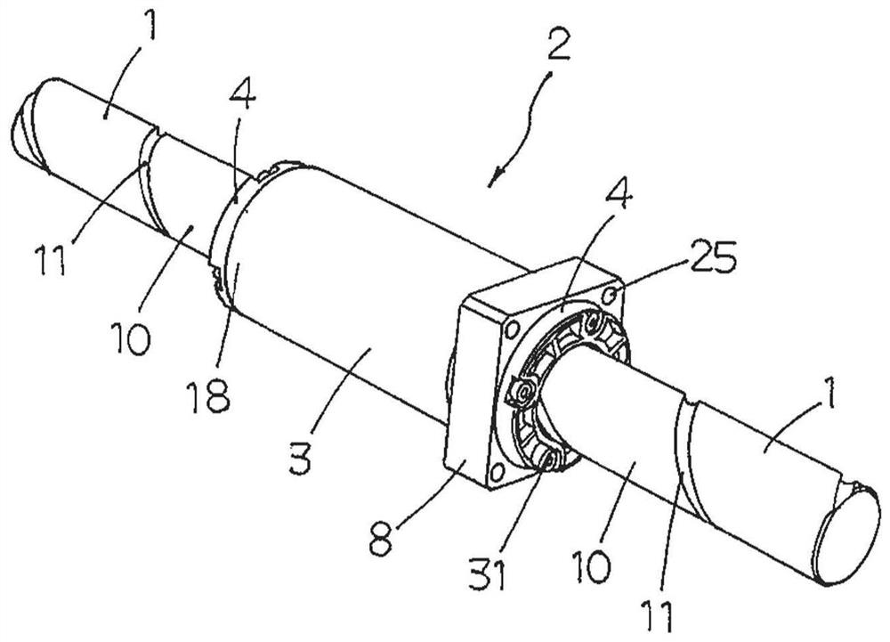
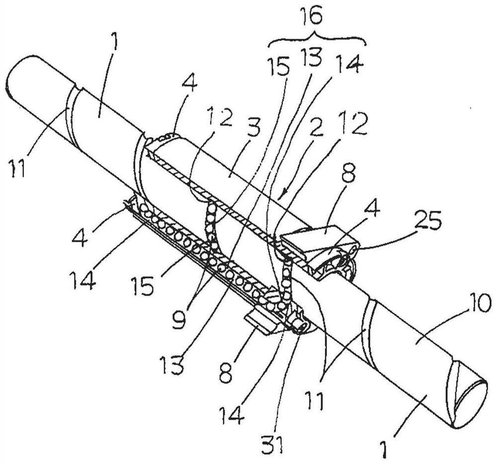
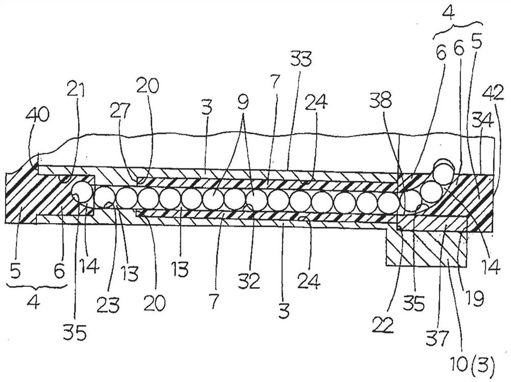
[0070] Hereinafter, an embodiment of the ball screw according to the present invention will be described with reference to the drawings. The ball screw of the present invention generally has: a rotatable screw shaft 1 on which a helical groove 11 (first helical groove) is formed in the axial direction on its outer peripheral surface 10; and a cylindrical nut 2 formed with an insertion The screw shaft 1 has an insertion hole 33 (first insertion hole), and a helical groove 12 (second helical groove) opposite to the helical groove 11 is formed in the axial direction on the inner peripheral surface 17 thereof. This ball screw is configured such that a plurality of balls 9 as rolling elements roll in a helical track path 15 formed by a helical groove 11 and a helical groove 12 as the screw shaft 1 rotate...


PUM


Abstract

In this ball screw, the structure in which the balls circulate inside the nut suppresses the generation of noise, and a return path is formed by a sleeve impregnated with lubricant inserted into the insertion hole of the nut body, so that The rolling balls supply lubricant, thereby achieving the effect of lubrication-free maintenance. A nut (2) inserted into a screw shaft (1) having a helical groove (11) includes: a cylindrical nut body (3) having a helical groove (12) and a return path (13); an end cap (4) , which has an end guide (6) disposed at the end (18) of the nut body (3); and a sleeve (7), which consists of a porous Shaped bodies are formed. The balls (9), which are supplied with lubricant while rolling in the return path (13) of the sleeve (7), thus achieve the effect of lubrication-free maintenance.

Description

technical field [0001] The present invention relates to a ball screw, which can be incorporated into various equipment such as a precision positioning table and other mechatronic products, detection devices, etc. Greasing unit composed of relatively moving nuts. Background technique [0002] Conventionally, as a linear motion device that stably supplies a lubricant by a self-lubricating method, for example, there is a device disclosed in JP-A-2013-174255. The linear motion device is a ball screw driving device of end cover deflection circulation mode, which includes: a nut with a spiral groove formed on its inner peripheral surface; a screw shaft formed on its outer peripheral surface opposite to the spiral groove of the nut. a helical groove; and a plurality of balls fitted between helical raceway surfaces formed by the helical grooves of the nut and the helical grooves of the screw shaft. In the inside of the nut, a return passage is integrally injected with oil-containi...

Claims


Application Information

Patent Timeline
Patent Type & Authority Patents(China)
IPC IPC(8): F16H25/20F16H25/22
CPCF16H25/20F16H25/2204F16C29/0609F16C29/0685F16C33/66
Inventor 坂井哲也武石正和
Owner NIPPON THOMPSON
Why Eureka
Try Eureka