Autonomous aerial cable inspection system

A kind of high-altitude cable and cable technology, which is applied in the direction of overhead line/cable equipment, control/regulation system, non-electric variable control, etc., and can solve problems such as high cost

Active Publication Date: 2017-10-20
GOOGLE LLC
View PDF9 Cites 10 Cited by
  • Summary
  • Abstract
  • Description
  • Claims
  • Application Information

AI Technical Summary

Problems solved by technology

Inspection of aerial fiber optic cables is a labor-intensive and often costly task
Another issue is security

Method used


Image

  • Autonomous aerial cable inspection system
  • Autonomous aerial cable inspection system
  • Autonomous aerial cable inspection system

Examples


Embodiment Construction
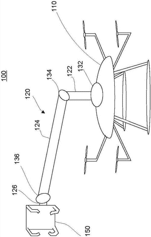
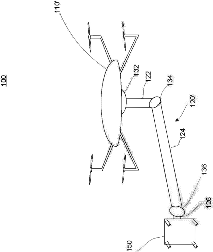
[0016] overview

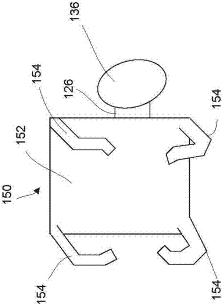
[0017] The technology of the present disclosure generally relates to unmanned aerial vehicles (UAVs), such as drones, adapted for close inspection of overhead cables. The vehicle includes a lightweight articulated robotic extension arm with an end effector adapted to maintain a fixed position relative to an overhead cable. For example, an end effector includes one or more sensors that provide real-time proximity feedback, stabilization control, and remote telemetry data. The end effector also includes one or more cameras, suitable for capturing 360-degree images of the overhead cable.

[0018] The extension arm is fabricated from lightweight materials and is articulated utilizing seven degrees of freedom, balanced at each joint for smooth and efficient movement. In one example, two 3-axis brushless DC gimbals are equipped, one at each end of the arm, and a single-axis joint with a brushless DC motor is located at the approximate midpoint of the arm (elbow j...


PUM


Abstract

An aerial inspection system is provided, including an unmanned aerial vehicle (UAV) having an articulated arm coupled thereto. An end effector is coupled to a second end of the articulated arm, the end effector sized and shaped to extend at least partially around an aerial cable in close proximity. One or more sensors are positioned along an inner surface of the end effector, and provide feedback to a control unit. In response, the control unit adjusts a position of at least one of the UAV, the articulated arm, and the end effector such that the end effector maintains a close, non-contact position with respect to the cable.

Description

Background technique [0001] Aerial cables, such as fiber optic cables, can be damaged by squirrel chewing, fireworks, bullets, weather, abrasion, etc. Should this occur, services provided over overhead cables may be disrupted. Current methods of inspecting overhead fiber optic cable casing for integrity or damage over long distances are slow, cumbersome, and sometimes lead to unsafe practices or methods. Since it is typically very difficult to find where the cable is damaged and then fix it, service interruptions can last for a long time. [0002] One of the biggest issues with the cost and delay of deploying, operating and maintaining fiber optic networks is manual labor. Inspection of aerial fiber optic cables is a labor-intensive and often costly task. Another issue is security. Many height workers are killed on the job each year, and many others suffer non-fatal loss of limbs from electrical burns and mechanical injuries. Contents of the invention [0003] One aspec...

Claims


Application Information

Patent Timeline
Patent Type & Authority Applications(China)
IPC IPC(8): H02G1/02
CPCH02G1/02B64U10/10B64U2101/00B64U2101/30H02G1/04G01R31/085B64C39/024G05D1/0094B64U10/13B64U2201/10B64U70/30B25J9/1684B64U10/00B64D45/0005B64D47/08G05D1/0011
Inventor D.W.约翰逊M.B.弗罗因德
Owner GOOGLE LLC
Why Eureka
Try Eureka