
Automatic lifting device for tobacco roller type equipment

An automatic lifting, roller technology, applied in the direction of lifting device, lifting frame, etc., can solve the problems of small contact area, complex internal structure, poor fixing effect, etc., to meet the safety requirements and realize the effect of automatic lifting function.

Pending Publication Date: 2017-11-03
CHINA TOBACCO HENAN IND
View PDF8 Cites 0 Cited by
  • Summary
  • Abstract
  • Description
  • Claims
  • Application Information

AI Technical Summary

Problems solved by technology

[0002] Drum equipment is widely used in cigarette production plants in my country, some of which are relatively heavy in weight and have complex internal structures
During the shutdown period of the factory, it is necessary to use mechanical equipment to manually raise the roller to prevent the support roller parts under the roller from being squeezed and deformed due to long-term pressure, which will affect the normal production operation; during maintenance and inspection, the roller needs to be fixed to prevent After workers enter, the center of gravity shifts and the roller shifts, which threatens the safety of employees. The original lifting and landing method of the roller adopts the manual mechanical single-point support method. The contact area between the support mechanism and the steel ring of the roller is small, which is difficult and weak, and it is fixed after rising. The effect is poor. When workers enter the interior of the drum for maintenance, it is easy to cause the center of gravity of the drum to shift and rotate, and there is a great potential safety hazard.

Method used


Image

  • Automatic lifting device for tobacco roller type equipment
  • Automatic lifting device for tobacco roller type equipment

Examples


Embodiment Construction

[0012] The present invention will be further described below in conjunction with the accompanying drawings.

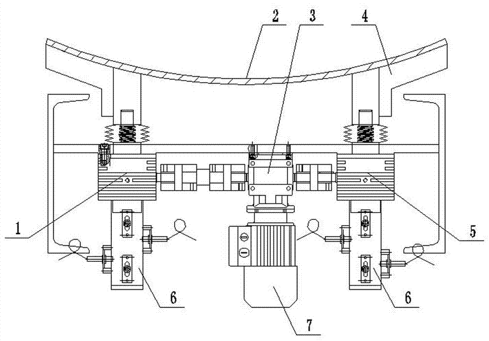
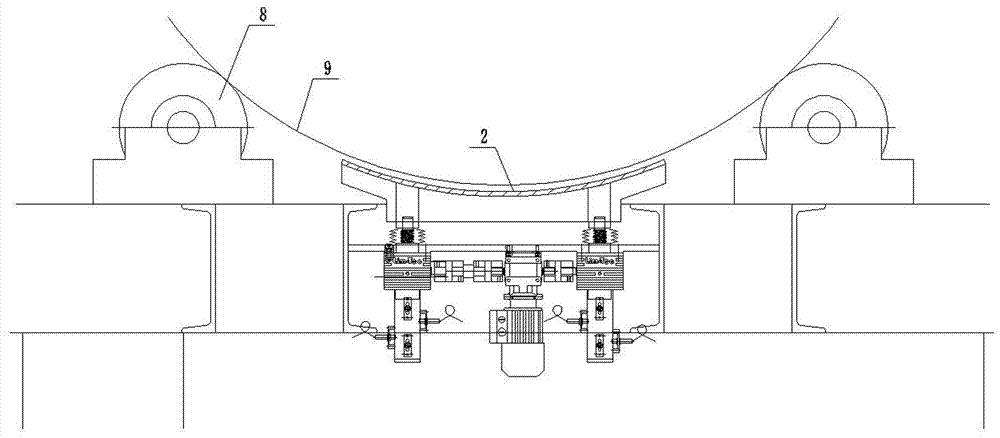
[0013] Such as figure 1 Shown, the present invention comprises arc-shaped backing plate 2 and bearing 6, is fixed with left helical lifting mechanism 1 and right helical lifting mechanism 5 for supporting arc-shaped backing plate 2 on bearing 6, in left helical lifting mechanism 1 and A right-angle gearbox reducer 3 is fixed on the support between the right-hand spiral lifting mechanism 5, and the right-angle gearbox reducer 3 is provided with a y-direction input shaft, a positive x-direction output shaft and a negative x-direction output shaft, and a positive x-direction output shaft. The output shaft and the negative x-direction output shaft rotate synchronously, the positive x-direction output shaft is in transmission connection with the power input end of the left helical lifting mechanism 1, the negative x-direction output shaft is in transmission connection with ...


PUM


Abstract

The invention discloses an automatic lifting device for tobacco roller type equipment. The automatic lifting device is characterized in that, the automatic lifting device comprises an arc cushion plate and a support, a left spiral lifting mechanism and a right spiral lifting mechanism which are used for supporting the arc cushion plate are fixed on the support, a right angle gearbox speed reducer is fixed to the position, between the left spiral lifting mechanism and the right spiral lifting mechanism, of the support, and the right angle gearbox speed reducer is provided with a y-direction input shaft, a positive x-direction output shaft and a negative x-direction output shaft; the positive x-direction output shaft rotates synchronously with the negative x-direction output shaft, the positive x-direction output shaft is in transmission connection with the power input end of the left spiral lifting mechanism, the negative x-direction output shaft is in transmission connection with the power input end of the right spiral lifting mechanism, and the y-direction input shaft is connected with a motor; the automatic lifting function of a roller is achieved through control over different gears of the left spiral lifting mechanism and the right spiral lifting mechanism, so that the safety requirements for the roller in different working states are met.

Description

technical field [0001] The invention belongs to the technical field of automatic elevating mechanical devices, in particular to an automatic elevating device for tobacco drum equipment. Background technique [0002] Drum equipment is widely used in cigarette production plants in my country, some of which have relatively large weight and complex internal structures. During the shutdown period of the factory, it is necessary to use mechanical equipment to manually raise the drum to prevent the support roller parts under the drum from being squeezed and deformed due to long-term pressure, which will affect the normal production operation; during maintenance and inspection, the drum needs to be fixed to prevent After workers enter, the center of gravity shifts and the roller shifts, which threatens the safety of employees. The original lifting and landing method of the roller adopts the manual mechanical single-point support method. The contact area between the support mechanism...

Claims


Application Information

Patent Timeline
Patent Type & Authority Applications(China)
IPC IPC(8): B66F3/08B66F3/46B66F7/14
CPCB66F3/08B66F3/46B66F7/14B66F2700/09
Inventor 朱建新赵淑华吴雪芹王晖秦冬刚东升
Owner CHINA TOBACCO HENAN IND
Learn More