An environmental chamber that simulates outdoor working conditions

A technology for working conditions and environmental chambers, which is applied in the field of building environment and equipment engineering, can solve the problems of low income, uniform airflow organization in the untestable area, and increase the initial investment and later maintenance costs of environmental chamber construction, so as to maintain uniformity and uniformity. Stable flow distribution and increased contact effect

Active Publication Date: 2019-04-12
南京冠福建设工程技术有限公司
View PDF6 Cites 0 Cited by
  • Summary
  • Abstract
  • Description
  • Claims
  • Application Information

AI Technical Summary

Problems solved by technology

The test environment chamber can improve the test conditions of some unit tests to a certain extent, but the income is low
Most of the machines to be tested in the outdoor and external environmental chambers adopt the method of air intake from all sides and air outlet in the middle. This patent increases the initial investment and later maintenance costs of the environmental chamber construction by switching the air duct to change the air supply mode. In addition, the structure of the test environmental chamber Does not provide uniform airflow distribution over the test area

Method used


Image

  • An environmental chamber that simulates outdoor working conditions
  • An environmental chamber that simulates outdoor working conditions
  • An environmental chamber that simulates outdoor working conditions

Examples


Embodiment Construction

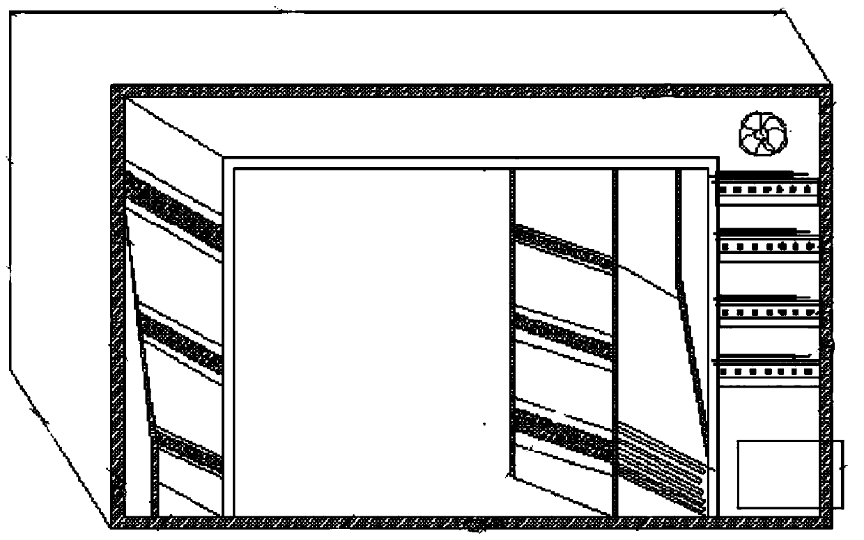
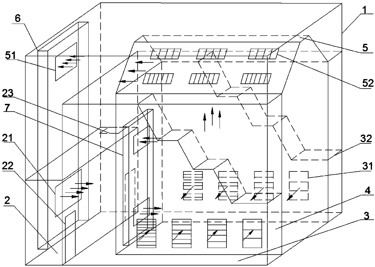
[0032] The present invention will be further described below in conjunction with embodiment and accompanying drawing.

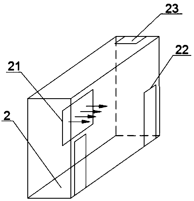
[0033] The environmental chamber for simulating outdoor working conditions in this embodiment includes a first air supply static pressure space 2 , a second variable section air supply static pressure space 3 , a test room 4 and a variable cross section return air static pressure space 5 . The first air-supply static pressure space 2 is provided with a first air-handling unit 6 , which includes an enclosure structure 1 , an air-supply port 21 , an air-supply door 22 and an inspection door 23 . The second air handling unit 7 is arranged outside the side partition of the test room 4, which includes a partition with air supply aluminum alloy louvers 31 and a double-pitched roof partition with return air aluminum alloy louvers 52. The air flow of the present invention is sent out from the air supply port 21 of the first air handling unit 6, first passes through t...


PUM


Abstract

The present invention discloses an environment chamber for simulation of an outdoor working condition. The chamber comprises a building enclosure, a first air supply static pressure space, a second variable cross-section air supply static pressure space, a test chamber, a variable cross-section air return static pressure space, a first air processing unit arranged on the building enclosure and a second air processing unit arranged on the separator of the test chamber. The air supply airflow enters the first air supply static pressure space from the air supply outlet on the building enclosure, enters the second variable cross-section air supply static pressure space from an air supply door, then enters the test chamber through an air supply aluminum alloy blind window and is sent out via an air return inlet through the variable cross-section air return static pressure space. The environment chamber employs an air return mode of air supply at the side and air return at the upper portion, and the two static pressure spaces and the variable cross-section air return static pressure space are employed to ensure the temperature and humidity in the test region in the environment chamber and uniform and stable air flow when test and ensure that the test working conditions satisfy the requirements of the serial standard outdoor side such as GB / T17758-2010 <unitary air conditioner>, etc.

Description

technical field [0001] The invention belongs to the technical field of building environment and equipment engineering, and relates to an environment room for performance testing of refrigeration equipment. Background technique [0002] With the implementation of national energy conservation and emission reduction policies, the energy efficiency requirements for refrigeration equipment are getting higher and higher, so the performance test of refrigeration equipment is very important. The test environment chamber can simulate various temperature, humidity and air velocity conditions to meet the requirements of refrigeration equipment test standards, while maintaining the stability and uniformity of the test area conditions. The laboratory obtains its energy efficiency value by testing the operating parameters of the refrigeration equipment. The closer and more stable the simulated conditions are to the standard working conditions, the more accurate the results will be. [00...

Claims


Application Information

Patent Timeline
Patent Type & Authority Patents(China)
IPC IPC(8): G01M9/00G01M99/00
CPCG01M9/00G01M99/005G01M99/008
Inventor 戚新秋张忠斌王子晨黄虎
Owner 南京冠福建设工程技术有限公司
Why Eureka
Try Eureka