An environment chamber for performance testing of air-conditioning and refrigeration equipment

A technology for testing the environment and equipment performance, which is applied to the testing of machines/structural components, measuring devices, instruments, etc. It can solve problems such as instability, small space in the test environment cabin, unsatisfactory improvement effects and improved benefits, etc., to achieve Uniform distribution and improved uniformity

Active Publication Date: 2019-06-21
TAIZHOU BAOKU REFRIGERATION EQUIP MFG
View PDF1 Cites 0 Cited by
  • Summary
  • Abstract
  • Description
  • Claims
  • Application Information

AI Technical Summary

Problems solved by technology

Although the test environment chamber can improve the airflow organization and environment required by a small number of units in the test room for testing to a certain extent, the improvement effect and income are not very satisfactory. Most of the machines to be tested in the outdoor test environment chamber It is the way of air in and out in the middle, and the space of the outdoor test environment chamber is not large. The two kinds of air ducts added in the patent to switch the air supply increase the building space and construction investment. In addition, the structure of the test environment chamber The way that the airflow enters the test area of ​​the machine under test cannot provide a uniform airflow in the test area, which will lead to uneven and unstable temperature and humidity of the airflow in the test area

Method used


Image

  • An environment chamber for performance testing of air-conditioning and refrigeration equipment
  • An environment chamber for performance testing of air-conditioning and refrigeration equipment
  • An environment chamber for performance testing of air-conditioning and refrigeration equipment

Examples


Embodiment Construction

[0030] Below in conjunction with embodiment technical solution of the present invention is made more specific description:

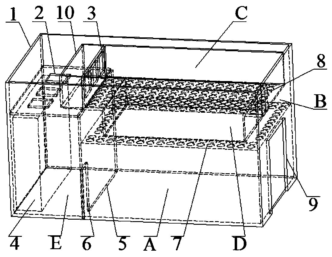
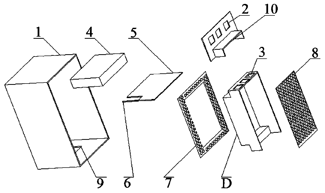
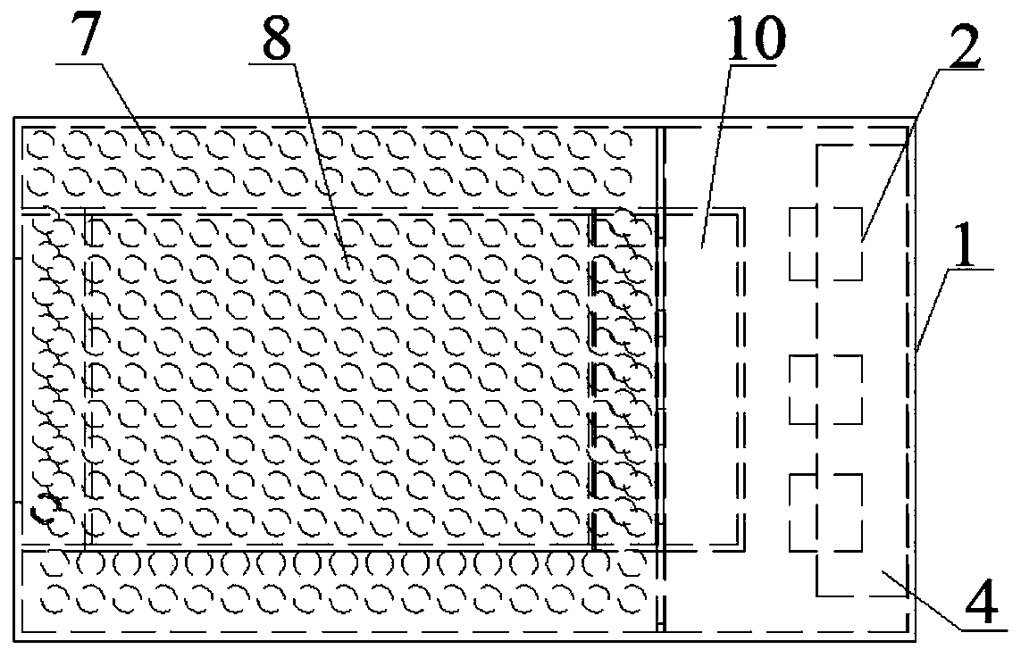
[0031] In this embodiment, one side of the air-conditioning and refrigeration equipment performance test environment chamber is the air handling unit installation section E, and the other side is the test section A of the machine under test and the return air passage located above the test section A. The air handling unit installation Section E is separated from test section A by a partition wall 5, and the top of the test section is formed by an annular air supply orifice 7, and the surface of the air supply orifice 7 is covered with air blown into the test section. The air supply through hole of the air, the ring in the middle of the air supply orifice 7 communicates with the return air passage, the return air outlet 3 at the outlet end of the return air passage communicates with the installation section E of the air handling unit, and the air supply T...


PUM


Abstract

The invention relates to an environmental chamber for testing the performance of air-conditioning refrigeration equipment. An air-handling unit installing section is disposed at a side in the environmental chamber. A test section of tested equipment and an air return channel over the test section are located at the other side in the environmental chamber. The top of the test section is formed by an annual air supply orifice plate. Air supply through-holes are fully arranged on the surface of the air supply orifice plate and are used for supplying air to the test section. An opening on the center of the air supply orifice plate communicates with the air return channel. An air return vent on the outlet end of the air return channel communicates with the air-handling unit installing section. An air supply channel is formed correspondingly in an annual area over the surface of the air supply orifice plate and communicates with an air supply port of the air-handling unit installing section. The air supply through-holes on the air supply orifice plate are arranged around the top of the test section. Air is supplied from around the top of the test section to the inside of the test section and is returned from the center by the air supply orifice plate. The method can provide a uniform and stable airflow for the test section and is able to better control the temperature and the humidity of the test section.

Description

technical field [0001] The invention belongs to the field of test devices for refrigeration and air conditioning, and in particular relates to an environment chamber for performance testing of air conditioning and refrigeration equipment. Background technique [0002] With the use of air conditioners more and more widely, the performance and energy-saving effect of various air conditioners have attracted more and more attention. Therefore, it is particularly important to have an enthalpy difference laboratory for air conditioner performance testing, and the enthalpy difference laboratory The design of the test environment chamber is the top priority. Patent application CN105133882A discloses a liquid-cooled source unit test environment chamber with the function of adjusting the wind direction. The patent realizes two air duct circulation modes of top air outlet and side return air or side outlet air top return air through air duct switching to meet different requirements. T...

Claims


Application Information

Patent Timeline
Patent Type & Authority Patents(China)
IPC IPC(8): G01M99/00
CPCG01M99/005
Inventor 张忠斌陈智明王子晨黄虎
Owner TAIZHOU BAOKU REFRIGERATION EQUIP MFG
Why Eureka
Try Eureka