A wireless sensor network time synchronization method and device

A wireless sensor, time synchronization technology, applied in synchronization devices, wireless communication, network topology, etc., can solve the problems of neglecting link noise interference, interfering with communication link stability, and crystal oscillator stability, etc., and achieve high precision The effect of time synchronization

Active Publication Date: 2020-02-04
SHENYANG INST OF AUTOMATION - CHINESE ACAD OF SCI
View PDF3 Cites 0 Cited by
  • Summary
  • Abstract
  • Description
  • Claims
  • Application Information

AI Technical Summary

Problems solved by technology

[0004] However, wireless sensor networks are generally deployed in harsh, unattended outdoor environments for a long time. Changes in ambient temperature and sensor node voltage have a greater impact on the stability of the crystal oscillator, and the external electromagnetic environment interferes with the stability of the communication link. , therefore, the factors that affect the time synchronization accuracy of wireless sensor networks mainly include the noise of the message transmission delay and the timing noise of the crystal oscillator
In the prior art, by assuming that the packet transmission delay obeys a specific Gaussian distribution, exponential distribution, etc., and then using methods such as maximum likelihood estimation and Bayesian estimation to estimate clock parameters and realize time synchronization, these methods are Ignoring the noise interference inherent in the clock timing process itself; there is also a method of using Kalman Filter to filter the noise in the crystal oscillator timing process. Although higher-precision time synchronization can be obtained, fixed communication is usually assumed when building a clock model link delay while ignoring link noise interference

Method used


Image

  • A wireless sensor network time synchronization method and device
  • A wireless sensor network time synchronization method and device
  • A wireless sensor network time synchronization method and device

Examples


Embodiment Construction

[0053] The present application is described in detail below in conjunction with the examples, but the present application is not limited to these examples.

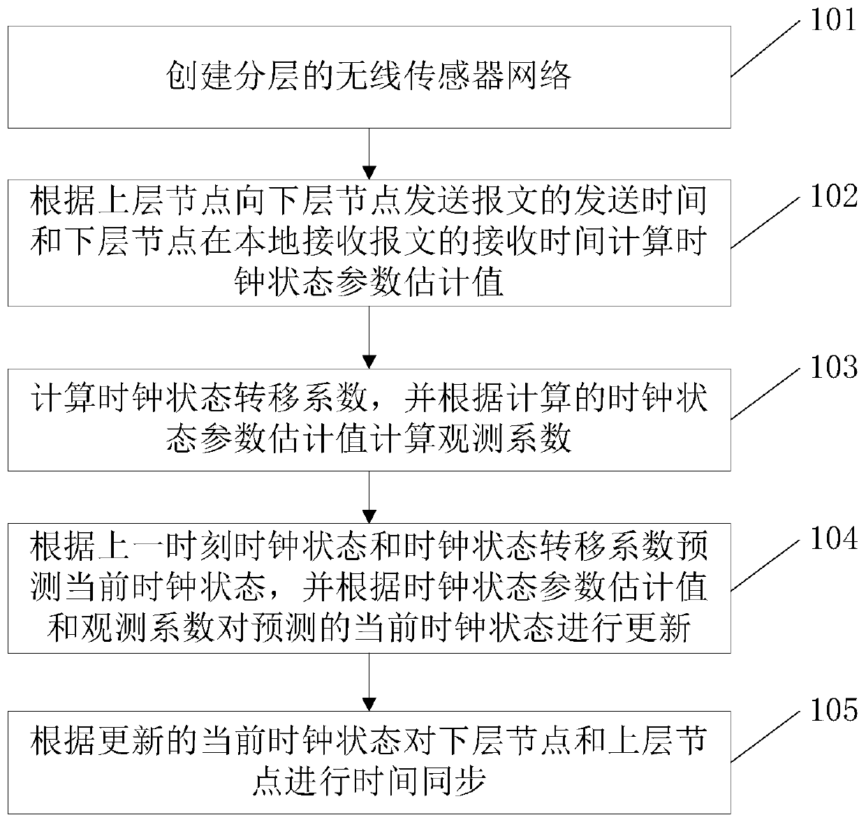
[0054] see figure 1 , an embodiment of the present invention provides a time synchronization method for a wireless sensor network, the method comprising:

[0055] 101. Create a layered wireless sensor network;

[0056] Among them, create a layered wireless sensor network, specifically:

[0057] The time source node periodically broadcasts messages containing its own hierarchical information;

[0058] The node that receives the message sent by the time source node sets its own layer number according to the layered information, and then continues to broadcast messages containing its own layered information to other nodes until a layered wireless sensor network structure is formed.

[0059] In the embodiment of the present invention, the layer number of the time source node is set to 0, and the time source node periodical...


PUM


Abstract

The invention discloses a time synchronization method of a wireless sensor network. The method comprises the steps of creating a hierarchical wireless sensor network; calculating a clock state parameter evaluation value according to a sending time at when an upper-layer node sends a packet to a lower-layer node and a receiving time at when the lower-layer node receives the packet locally; calculating a clock state transfer coefficient, and calculating an observation coefficient according to the calculated clock state parameter evaluation value; predicting a current clock state according to a clock state at a previous time point and the clock state transfer coefficient, and updating the predicted current clock state according to the clock state parameter estimation value and the observation coefficient; and performing time synchronization on the upper-layer node and the lower-layer node according to the updated current clock state. Through adoption of the time synchronization method of the wireless sensor network, the time of the hierarchical wireless sensor network is synchronized at high precision.

Description

technical field [0001] The present application relates to a time synchronization method and device for a wireless sensor network, belonging to the field of wireless sensor networks. Background technique [0002] In the practical application of wireless sensor networks, the data collected by sensor nodes are closely related to time. At the same time, technologies such as node positioning, data fusion, TDMA scheduling, and cooperative sleep all require network time synchronization. However, due to the influence of hardware characteristics and working environment, the local time of sensor nodes often deviates from the standard time. Therefore, in order to ensure the normal and orderly progress of the network, maintaining time synchronization is of great significance for the wide application of wireless sensor networks. [0003] In a wireless sensor network, the timing unit of a sensor node usually includes a crystal oscillator and a counting register. Every time the crystal os...

Claims


Application Information

Patent Timeline
Patent Type & Authority Patents(China)
IPC IPC(8): H04W56/00H04W84/18
CPCH04W56/001H04W84/18
Inventor 曾鹏王照伟王金涛于海斌
Owner SHENYANG INST OF AUTOMATION - CHINESE ACAD OF SCI
Why Eureka
Try Eureka