
Fixtures for blow molds

A technology of blow molds and fixtures, which is applied in the field of blow mold fixtures, can solve problems such as slow action process, complex structure, and low safety, and achieve the effects of good safety, good continuity, and high production efficiency

Active Publication Date: 2019-09-20
NINGBO FANGZHENG TOOL
View PDF6 Cites 0 Cited by
  • Summary
  • Abstract
  • Description
  • Claims
  • Application Information

AI Technical Summary

Problems solved by technology

[0002] After the liquid plastic is sprayed out, the plastic body is blown and attached to a mold cavity of a certain shape by using the wind force blown out by the machine to make a product. This kind of machine is called a blow molding machine. Automobile tailpipes need to be blown. Fix one end of the tail pipe, and use a mold to blow the other end of the tail pipe. However, at present, the tail pipe needs to be manually inserted into the position of the fixture, and then stretched after being clamped by the fixture. Blow molding treatment, the existing technology, such as the website of the State Intellectual Property Office, discloses an insert fixture for blow molding molds, which uses a pull-sleeve oil cylinder to draw and spread the clamp jaws to realize the clamping and loosening of pipe fittings, and the structure is complex. High cost, slow action process, low efficiency and low safety

Method used


Image

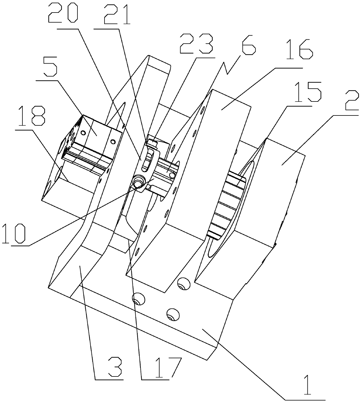
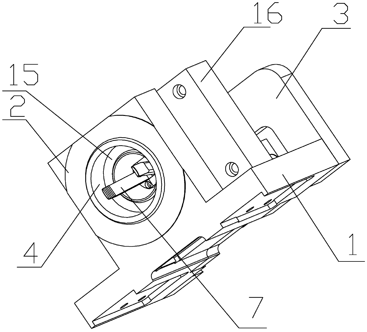
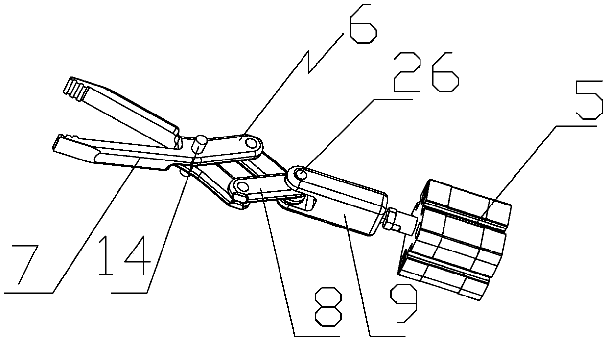
  • Fixtures for blow molds
  • Fixtures for blow molds
  • Fixtures for blow molds

Examples


Embodiment Construction

[0020] The present invention will be further described below in conjunction with the accompanying drawings and specific embodiments.

[0021] As shown in the figure, the present invention provides a clamp for blow molding, which includes a base 1 and a clamp 6, the upper surface of the base 1 is respectively provided with a base plate 2 and a support plate 3, the base plate 2 Parallel to the support plate 3, the substrate 2 is provided with a through hole 4, the tail of the clamp 6 is fixed on the surface of the support plate 3 near the substrate 2, and the head of the clamp 6 extends into the through hole 4, the surface of the support plate 3 away from the base plate 2 is provided with a first cylinder 5, the piston rod of the first cylinder 5 is connected to the tail of the clamp 6, and the axis of the clamp 6 is connected to the axis of the through hole 4 On the same straight line, the first cylinder 5 drives the clamp 6 to close and open. The advantage of the present inven...


PUM


Abstract

A clamp used for a blowing mold comprises a base (1) and a clamp body (6). A base plate (2) and a supporting plate (3) are arranged on the upper surface of the base (1). The base plate (2) and the supporting plate (3) are parallel to each other. A through hole (4) is formed in the base plate (2). The tail portion of the clamp body (6) is fixed to the surface, close to the base plate (2), of the supporting plate (3). The head portion of the clamp body (6) extends into the through hole (4). A first cylinder (5) is arranged on the surface, away from the base plate (2), of the supporting plate (3). A piston rod of the first cylinder (5) is connected with the tail portion of the clamp body (6). The axis of the clamp body (6) and the axis of the through hole (4) are on the same straight line. The first cylinder (5) drives the clamp body (6) to be closed and opened. Compared with the prior art, the supporting plate is arranged, the through hole used for containing a pipe fitting is formed in the supporting plate, the clamp body is pulled through the first cylinder to conduct clamping and releasing, and therefore the pipe fitting is clamped and released through the clamp body; and the clamp is simple in structure and low in cost, only one first cylinder is needed, and efficiency is high.

Description

technical field [0001] The invention relates to a clamp, in particular to a clamp for a blow mold. Background technique [0002] After the liquid plastic is sprayed out, the plastic body is blown and attached to a mold cavity of a certain shape by using the wind force blown out by the machine to make a product. This kind of machine is called a blow molding machine. Automobile tailpipes need to be blown. Fix one end of the tail pipe, and use a mold to blow the other end of the tail pipe. However, at present, the tail pipe needs to be manually inserted into the position of the fixture, and then stretched after being clamped by the fixture. Blow molding treatment, the existing technology, such as the website of the State Intellectual Property Office, discloses an insert fixture for blow molding molds, which uses a pull-sleeve oil cylinder to draw and spread the clamp jaws to realize the clamping and loosening of pipe fittings, and the structure is complex. The cost is high, th...

Claims


Application Information

Patent Timeline
Patent Type & Authority Patents(China)
IPC IPC(8): B29C49/56
Inventor 徐丰张修恩葛小翔程苗王锦浪蒋新通
Owner NINGBO FANGZHENG TOOL
Learn More