Dust remover device

A technology of dust collector and carriage, which is applied to coupling devices, parts of connecting devices, devices preventing contact with live contacts, etc. and other problems, to avoid sudden power failure, increase aesthetics, and achieve the effect of safe and stable power supply

Inactive Publication Date: 2017-11-17
高峰
View PDF0 Cites 9 Cited by
  • Summary
  • Abstract
  • Description
  • Claims
  • Application Information

AI Technical Summary

Problems solved by technology

[0002] At present, the energization of the dust collector is basically to penetrate the electrical connection contact connected to it into the power transmission cavity of the socket for matching connection. The electric connection contact cannot be locked in the power transmission cavity later. When the electric connection contact is accidentally kicked and hits the cable connected between the electric connection contact and the dust collector, the electric connection contact will be separated from the matching connection in the power transmission cavity, resulting in Sudden power failure of the dust collector, so the existing coordination method has the risk of unstable power supply connection. In addition, when the dust collector is not in use, the electrical contact is often pulled out from the power transmission cavity, which will cause the transmission The electric cavity is exposed, and the power transmission cavity is often connected to the power supply and is always in the energized state, so there is a big potential safety hazard

Method used


Image

  • Dust remover device
  • Dust remover device
  • Dust remover device

Examples


Embodiment Construction

[0020] The preferred embodiments of the present invention will be described in detail below in conjunction with the accompanying drawings, so that the advantages and features of the present invention can be more easily understood by those skilled in the art, so as to define the protection scope of the present invention more clearly.

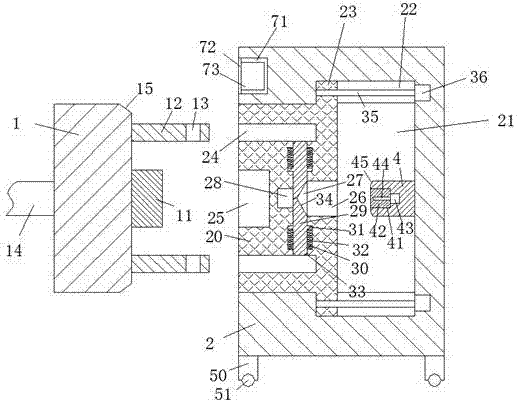
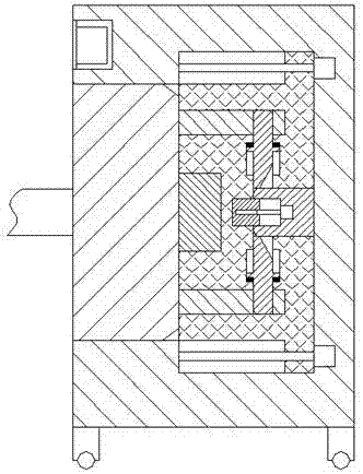
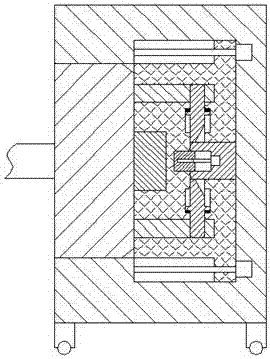
[0021] refer to Figure 1-4 The shown dust collector device includes a power transmission frame 2, a sliding frame 20 arranged in the power transmission frame 2, and an electrical coupling head 1. An electrical coupling contact 11 is arranged in the center of the right end surface of the electrical coupling head 1, so that The right end face of the electric joint head 1 is located at the front and rear ends of the electric joint contact 11 and is oppositely provided with two inserting posts 12, and the right ends of the two inserting posts 12 are provided with locking holes 13 and the two inserting posts 12 are provided with locking holes 13 and ...


PUM


Abstract

The invention discloses a dust remover device, which comprises a power transmission frame, a sliding frame arranged in the power transmission frame, and an electrical connection head. The front and rear ends of the electric contact are oppositely provided with two insertion posts, the right ends of the two insertion posts are provided with locking holes and the two locking holes are oppositely arranged, and the power transmission A pillar is fixedly installed at the bottom of the frame, and rollers are arranged at the bottom of the pillar. A sliding chamber for the electric coupler to penetrate is arranged in the power transmission frame, and the front and rear ends on the right side of the sliding chamber are oppositely arranged. There are two chutes connecting the sliding cavity, the overall structure of the present invention is simple, the power supply stability is good, the occurrence of electric shock accidents in existing life is effectively reduced, and the safety of people's lives is guaranteed, and the operation safety of the whole device is The utility model has the advantages of reliability, reasonable structure setting, simple and convenient operation, and is suitable for popularization and use.

Description

technical field [0001] The invention relates to the field of dust collectors, in particular to a dust collector device. Background technique [0002] At present, the energization of the dust collector is basically to penetrate the electrical connection contact connected to it into the power transmission cavity of the socket for matching connection. The electric connection contact cannot be locked in the power transmission cavity later. When the electric connection contact is accidentally kicked and hits the cable connected between the electric connection contact and the dust collector, the electric connection contact will be separated from the matching connection in the power transmission cavity, resulting in Sudden power failure of the dust collector, so the existing coordination method has the risk of unstable power supply connection. In addition, when the dust collector is not in use, the electrical contact is often pulled out from the power transmission cavity, which wil...

Claims


Application Information

Patent Timeline
Patent Type & Authority Applications(China)
IPC IPC(8): H01R13/44H01R13/627H01R13/629
CPCH01R13/627H01R13/44H01R13/6278H01R13/629
Inventor 高峰
Owner 高峰
Why Eureka
Try Eureka