Dust catcher equipment

A dust collector and equipment technology, applied in the direction of preventing contact with live contacts, electrical components, coupling devices, etc., can solve problems such as affecting the use of the dust collector, breaking the plug of the dust collector, and plugging and unplugging the plug which is prone to electric shock accidents. , to achieve the effect of increasing safety and stability and preventing sudden power failure

Inactive Publication Date: 2017-10-03
毛远之
View PDF2 Cites 3 Cited by
  • Summary
  • Abstract
  • Description
  • Claims
  • Application Information

AI Technical Summary

Problems solved by technology

[0002] The dust collector needs to be moved around when in use. Since the plug and the socket of the existing dust collector are generally connected by friction fit, no other locking device is provided, so when the dust collector is moved when the staff touches it, it is ea

Method used


Image

  • Dust catcher equipment
  • Dust catcher equipment
  • Dust catcher equipment

Examples


Embodiment Construction

[0019] The preferred embodiments of the present invention will be described in detail below in conjunction with the accompanying drawings, so that the advantages and features of the present invention can be more easily understood by those skilled in the art, so as to define the protection scope of the present invention more clearly.

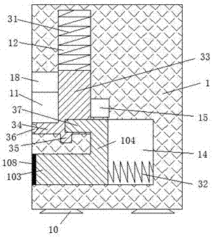
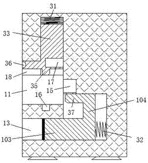
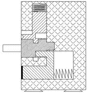
[0020] refer to Figure 1-5 The dust remover equipment shown includes a power transmission unit 1 and a power transmission unit 2 for penetrating into the power transmission unit 1 for cooperating connection. The bottom of the transmission unit 4 is provided with suction cups 10 that are symmetrical on the left and right, and the suction cups are used for To absorb with the ground, thereby increasing the stability of the transmission station 1, the slot 11 with the notch facing the left is provided in the transmission station 4, and the power transmission slot 15 connected to the mains is provided on the right end of the slot 11 , the inner top e...


PUM


Abstract

The invention discloses a dust remover equipment, which comprises a power transmission station and a power transmission part for penetrating into the transmission station for coordinating connection. Suction cups are arranged on the bottom of the transmission station, and the bottom of the transmission station is provided with notches to The left slot, the right end of the inside of the slot is provided with a power transmission slot connected to the mains, the top of the slot inside is provided with an upper sliding slot communicating with the slot, The transmission station below is also provided with a pushing slot with the notch facing left, and a sliding slot communicating with the slot is arranged at the right end of the pushing slot. The structure of the present invention is simple, the production cost is low, and the power supply is safe and stable. , effectively prevent the occurrence of electric shock accidents, and the plug-in operation is more convenient, avoiding the sudden power failure of the dust collector caused by the power transmission handle being separated from the power transmission groove when the cable is kicked, and satisfying the existing dust collector plug-in Access to electricity needs.

Description

technical field [0001] The invention relates to the field of dust collectors, in particular to dust collector equipment. Background technique [0002] The dust collector needs to be moved around when in use. Since the plug and the socket of the existing dust collector are generally connected by friction fit, no other locking device is provided, so when the dust collector is moved when the staff touches it, it is easy to break it. The plug of the dust collector breaks open, which affects the use of the dust collector, and the existing sockets connected to the dust collector are all directly charged, so electric shock accidents are likely to occur when plugging and unplugging the plug. Contents of the invention [0003] The technical problem to be solved by the present invention is to provide a dust collector device, which can solve the above-mentioned problems in the prior art. [0004] In order to solve the above problems, the present invention adopts the following techni...

Claims


Application Information

Patent Timeline
IPC IPC(8): H01R13/44H01R13/639
CPCH01R13/639H01R13/44
Inventor 毛远之
Owner 毛远之
Why Eureka
Try Eureka