
Blower equipment

A hair dryer and equipment technology, applied in hairdressing equipment, clothing, electrical components, etc., can solve problems such as electric shock accidents, no setting, affecting the use of hair dryers, etc., to avoid electric shock accidents, increase stability, and reduce electric shock accidents.

Inactive Publication Date: 2017-09-19
徐州市苏文机械设备制造有限公司
View PDF6 Cites 3 Cited by
  • Summary
  • Abstract
  • Description
  • Claims
  • Application Information

AI Technical Summary

Problems solved by technology

[0002] Before using the hair dryer, you need to match the plug of the hair dryer with the socket to provide electricity for the hair dryer. Since the length of the wire connected to the plug of the hair dryer is fixed, and the hair needs to be blown from various angles when blowing the hair, the angle of the hair dryer needs to be adjusted frequently In this way, since the traditional socket and the plug of the hair dryer are directly connected by friction fit, no other locking device is provided, so when people use it, it is easy to pull the plug of the hair dryer away from the socket, so that the power failure affects the use of the hair dryer. Moreover, the existing sockets connected to the hair dryer are all directly charged, so electric shock accidents are likely to occur when inserting the plug.

Method used


Image

  • Blower equipment
  • Blower equipment
  • Blower equipment

Examples


Embodiment Construction

[0023] The preferred embodiments of the present invention will be described in detail below in conjunction with the accompanying drawings, so that the advantages and features of the present invention can be more easily understood by those skilled in the art, so as to define the protection scope of the present invention more clearly.

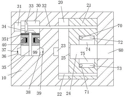
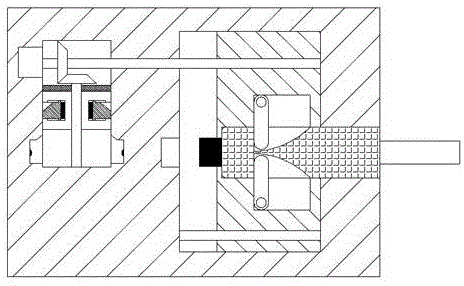
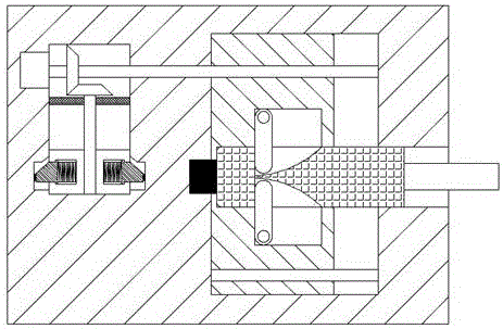
[0024] refer to Figure 1-7 The blower equipment shown includes a shell 10 and a power transmission device connected to the blower. The left and right ends of the bottom of the shell 10 are respectively equipped with suction cups 11, and the suction cups 11 are used to absorb and fix the shell 10. , the shell 10 is provided with a left chute 30, the shell 10 is also provided with a right chute 20 on the right side of the left chute 30, and the right end surface of the shell 10 is provided with Connect the slot 60 of the right chute 20, the left end of the right chute 20 is provided with a power transmission slot 23 opposite to the slot 60, the ri...


PUM


Abstract

The invention discloses blower equipment, and the equipment comprises a housing sleeve and a power transmission device connected with a blower. The left and right ends of the bottom of the housing sleeve are respectively provided with a sucking disc, and the housing sleeve is provided with a left chute. The interior of the housing sleeve is also provided with a right chute located at the right side of the left chute. The right end face of the housing sleeve is provided with a slot communicated with the right chute. The left end part of the right chute is provided with a power transmission groove opposite to the slot. The interior of the right chute is provided with a first sliding block which can slide left and right. The equipment is simpler in overall structure, is safe and stable in supply line connection, effectively avoids the electric shock accidents in life, and guarantees the personal safety of the people. The connection operation of a circuit between a holding part and the power transmission groove is automatically completed through the operation of a first motor. The power-on plugging connection between the housing sleeve and the power transmission device is simple, and there is no electric shock accident in the power-on plugging connection process, so the equipment meets the current application demands, and is suitable for popularization and application.

Description

technical field [0001] The invention relates to the field of hair dryers, in particular to a hair dryer device. Background technique [0002] Before using the hair dryer, you need to match the plug of the hair dryer with the socket to provide electricity for the hair dryer. Since the length of the wire connected to the plug of the hair dryer is fixed, and the hair needs to be blown from various angles when blowing the hair, the angle of the hair dryer needs to be adjusted frequently In this way, since the traditional socket and the plug of the hair dryer are directly connected by friction fit, no other locking device is provided, so when people use it, it is easy to pull the plug of the hair dryer away from the socket, so that the power failure affects the use of the hair dryer. And existing socket that connects hair dryer all is directly charged, therefore easily produces electric shock accident when inserting plug. Contents of the invention [0003] The technical proble...

Claims


Application Information

Patent Timeline
Patent Type & Authority Applications(China)
IPC IPC(8): H01R13/639H01R13/629H01R13/70A45D20/12
CPCA45D20/12H01R13/629H01R13/639H01R13/701
Inventor 何建龙
Owner 徐州市苏文机械设备制造有限公司
Learn More