
Power distribution box with heat dissipation function and convenient and quick to mount

A power distribution box, a convenient technology, applied in substation/power distribution device housing, electrical components, substation/switch layout details, etc., can solve problems such as inconvenient installation, poor heat dissipation, slow installation speed, etc.

Active Publication Date: 2017-11-17
BEIJING JINGCHUANGDA SCI & TECH
View PDF5 Cites 4 Cited by
  • Summary
  • Abstract
  • Description
  • Claims
  • Application Information

AI Technical Summary

Problems solved by technology

[0005] In order to overcome the disadvantages of slow installation speed, inconvenient installation and poor heat dissipation in the existing distribution box, the technical problem to be solved by the present invention is to provide a distribution box that can dissipate heat and install it conveniently

Method used


Image

  • Power distribution box with heat dissipation function and convenient and quick to mount
  • Power distribution box with heat dissipation function and convenient and quick to mount
  • Power distribution box with heat dissipation function and convenient and quick to mount

Examples


Embodiment 1

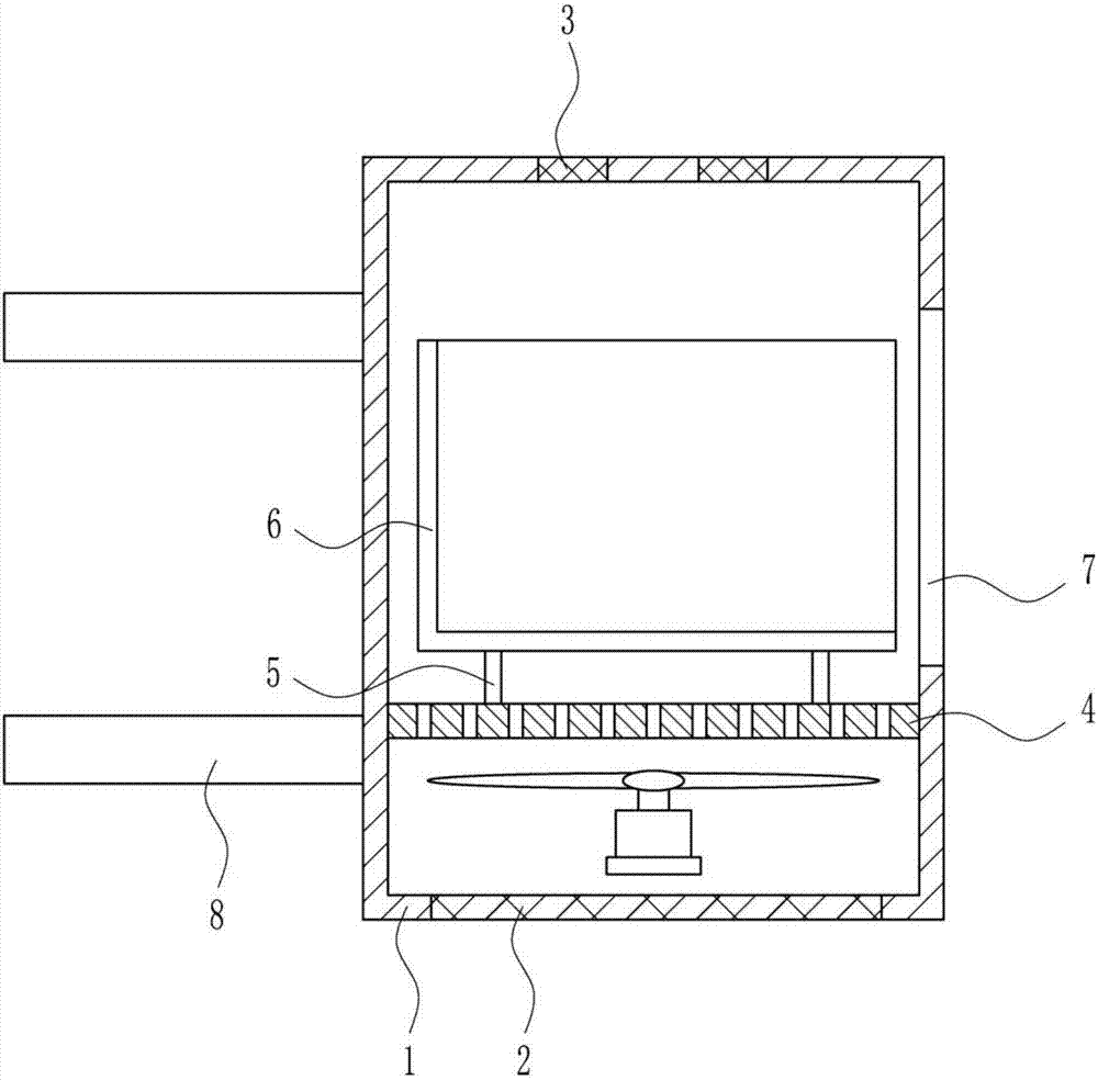
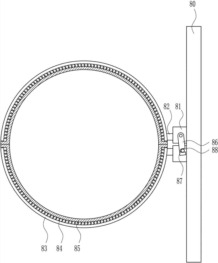
[0036] A distribution box that can dissipate heat and install it conveniently, such as Figure 1-7 As shown, it includes a box body 1, a first net plate 2, a second net plate 3, a blowing device 4, a bracket 5, a mounting frame 6 and a clamping device 8. The bottom of the box body 1 is embedded with the first net plate 2, and the box The top of the body 1 is embedded with a second mesh plate 3, the lower part of the box body 1 is provided with a blowing device 4, the top of the blowing device 4 is provided with a bracket 5, the upper end of the bracket 5 is provided with a mounting frame 6, and the right wall of the box body 1 has an opening 7, The opening 7 is located on the right side of the installation frame 6 , and the left wall of the box body 1 is provided with a clamping device 8 .

Embodiment 2

[0038] A distribution box that can dissipate heat and install it conveniently, such as Figure 1-7 As shown, it includes a box body 1, a first net plate 2, a second net plate 3, a blowing device 4, a bracket 5, a mounting frame 6 and a clamping device 8. The bottom of the box body 1 is embedded with the first net plate 2, and the box The top of the body 1 is embedded with a second mesh plate 3, the lower part of the box body 1 is provided with a blowing device 4, the top of the blowing device 4 is provided with a bracket 5, the upper end of the bracket 5 is provided with a mounting frame 6, and the right wall of the box body 1 has an opening 7, The opening 7 is located on the right side of the installation frame 6 , and the left wall of the box body 1 is provided with a clamping device 8 .

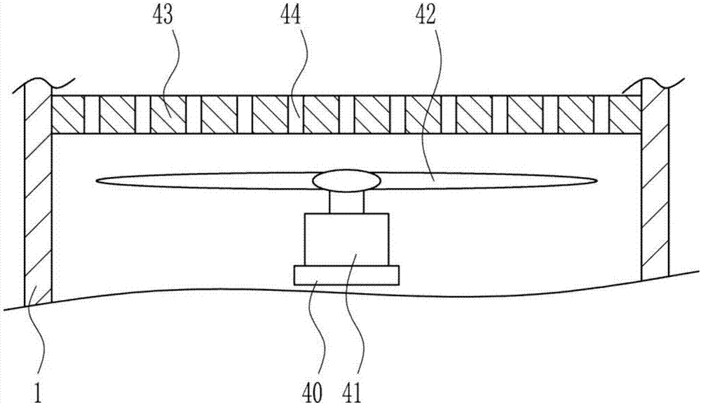
[0039] Blowing device 4 comprises support plate 40, motor 41, fan blade 42 and dividing plate 43, and casing 1 inner rear wall bottom is provided with support plate 40, and support plate 4...

Embodiment 3

[0041] A distribution box that can dissipate heat and install it conveniently, such as Figure 1-7 As shown, it includes a box body 1, a first net plate 2, a second net plate 3, a blowing device 4, a bracket 5, a mounting frame 6 and a clamping device 8. The bottom of the box body 1 is embedded with the first net plate 2, and the box The top of the body 1 is embedded with a second mesh plate 3, the lower part of the box body 1 is provided with a blowing device 4, the top of the blowing device 4 is provided with a bracket 5, the upper end of the bracket 5 is provided with a mounting frame 6, and the right wall of the box body 1 has an opening 7, The opening 7 is located on the right side of the installation frame 6 , and the left wall of the box body 1 is provided with a clamping device 8 .

[0042] Blowing device 4 comprises support plate 40, motor 41, fan blade 42 and dividing plate 43, and casing 1 inner rear wall bottom is provided with support plate 40, and support plate 4...


PUM


Abstract

The invention relates to a power distribution box, particularly to the power distribution box with a heat dissipation function and convenient and quick to mount, and aims to provide the power distribution box with the heat dissipation function and convenient and quick to mount by solving the technical problems. For solving the technical problems, the invention provides the power distribution box with the heat dissipation function and convenient and quick to mount. The power distribution box comprises a box body, a first screen plate, a second screen plate, an air blowing apparatus, a bracket and the like; the first screen plate is embedded in the bottom of the box body; the second screen plate is embedded in the top of the box body; the air blowing apparatus is arranged on the lower part of the interior of the box body; the bracket is arranged on the top of the air blowing apparatus; a mounting frame is arranged at the upper end of the bracket; an opening, which is positioned just in the right side of the mounting frame, is formed in the right wall of the box body; and a clamping apparatus is arranged on the left wall of the box body. The power distribution box achieves the effects of quick mounting speed, convenience in mounting and high heat dissipation; a first baffle and second baffle can baffle rain water, so that rainwater can be prevented from entering the box body; by virtue of the clamping apparatus, the power distribution box can be mounted and fixed more conveniently and quickly by people; and in addition, the power distribution box is safe and stable and high in generalizability.

Description

technical field [0001] The invention relates to a distribution box, in particular to a distribution box capable of heat dissipation and convenient installation. Background technique [0002] The distribution box is a large number of parameters in the data. It generally constitutes a low-voltage distribution box. box. During normal operation, the circuit can be connected or disconnected by means of a manual or automatic switch. The distribution box is generally used to distribute electric energy reasonably and facilitate the opening and closing operation of the circuit. It has a high level of safety protection and can intuitively display the conduction state of the circuit. [0003] In order to better distribute electric energy, people will install distribution boxes to distribute electric energy. However, the existing distribution boxes have the disadvantages of slow installation speed, inconvenient installation, and poor heat dissipation. Therefore, it is urgent to develo...

Claims


Application Information

Patent Timeline
Patent Type & Authority Applications(China)
IPC IPC(8): H02B1/46H02B1/56H02B1/28
CPCH02B1/28H02B1/46H02B1/565
Inventor 郭昌磊王英付友
Owner BEIJING JINGCHUANGDA SCI & TECH
Learn More