A Directional High Gain Microstrip Antenna

A microstrip antenna and high-gain technology, which is applied in the direction of antenna, antenna grounding device, antenna grounding switch structure connection, etc., can solve the problems of small gain and poor directivity, and achieve increased gain, good symmetry, and suppression of backward radiation. Effect

Active Publication Date: 2019-11-15
XIDIAN UNIV
View PDF3 Cites 0 Cited by
  • Summary
  • Abstract
  • Description
  • Claims
  • Application Information

AI Technical Summary

Problems solved by technology

[0005] The purpose of the present invention is to address the above-mentioned deficiencies in the prior art, and propose a directional high-gain microstrip antenna, which is used to solve technical problems such as small gain and poor directivity that exist in the existing microstrip antenna

Method used


Image

  • A Directional High Gain Microstrip Antenna
  • A Directional High Gain Microstrip Antenna
  • A Directional High Gain Microstrip Antenna

Examples


Embodiment 1

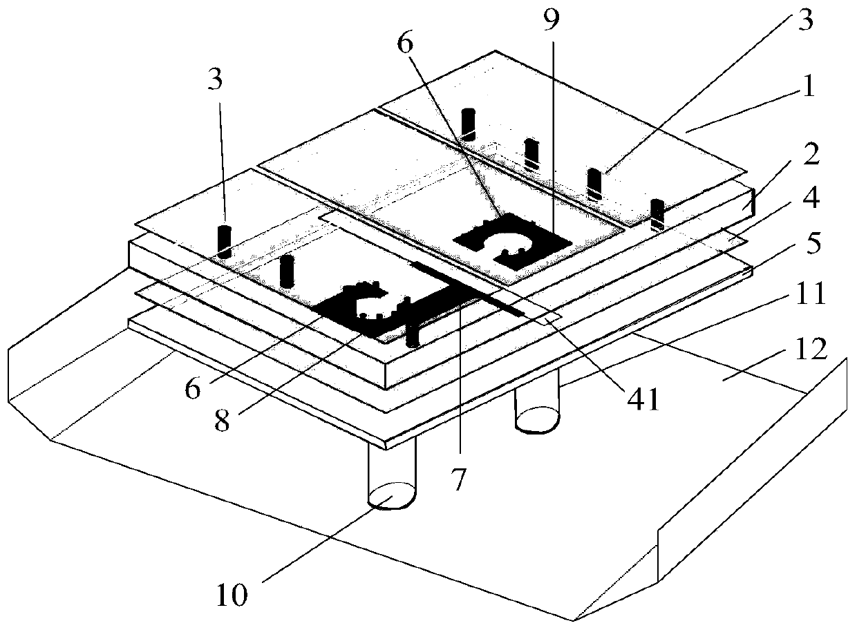
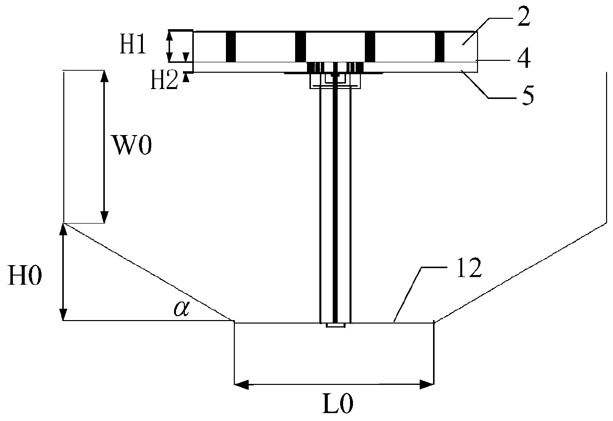
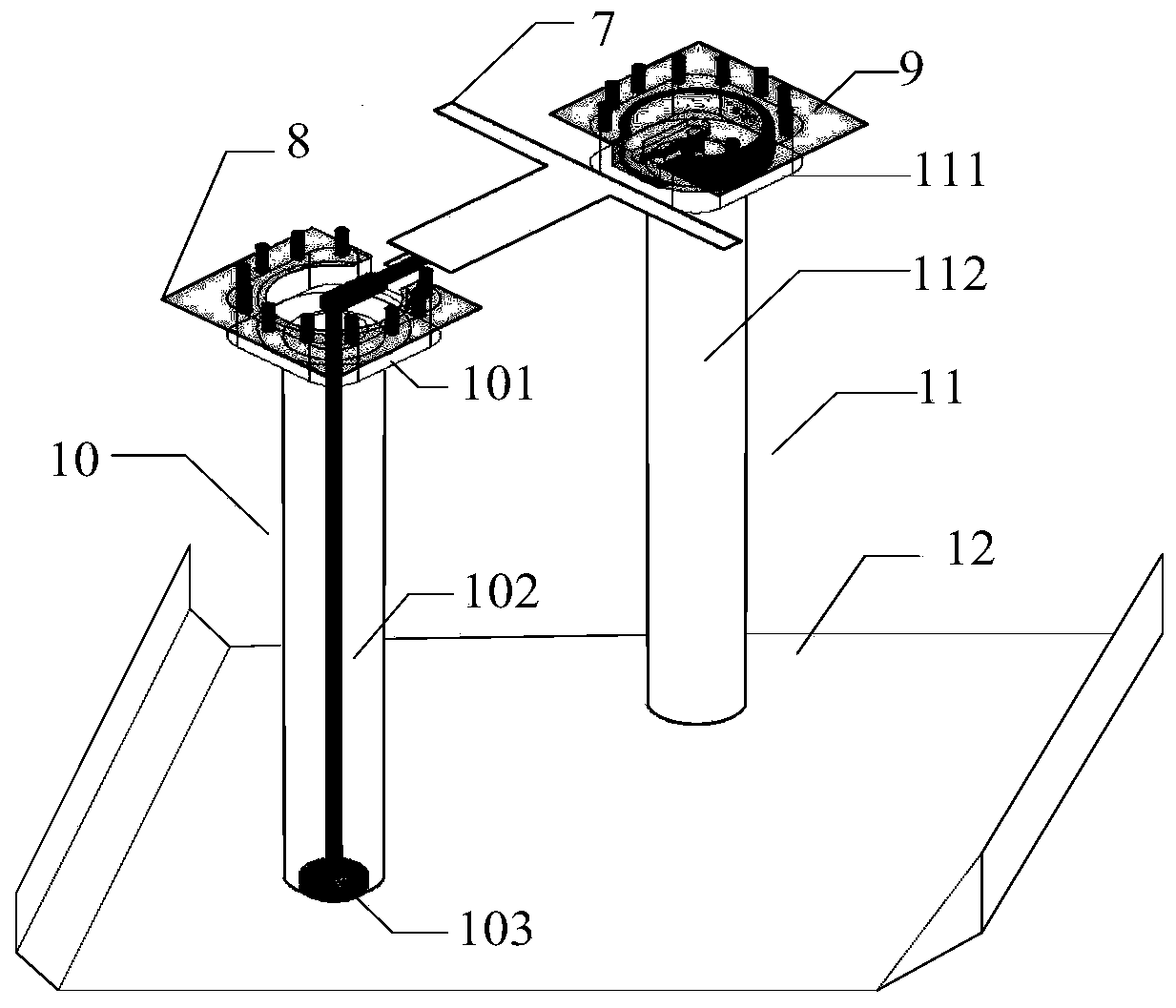
[0031] refer to figure 1: A directional high-gain microstrip antenna, comprising a radiation unit 1, an upper dielectric substrate 2, a first metallized via hole 3, a floor 4, a lower dielectric substrate 5, a second metallized via hole 6, and a T-shaped microstrip line 7 , the first metal pad 8 and the second metal pad 9; the upper dielectric substrate 2 and the lower dielectric substrate 5 form an up and down stacked structure, and the radiation unit 1 is composed of three rectangular patches arranged in sequence, printed on the upper dielectric substrate 2 The floor 4 is printed on the upper surface of the lower dielectric substrate 5, the center of which is provided with a rectangular slit 41, and the T-shaped microstrip line 7 is printed on the center of the lower surface of the lower dielectric substrate 5 for transmitting radio frequency signals , and radiate electromagnetic energy outward through the rectangular slit 41, and simultaneously excite the radiation unit 1 a...

Embodiment 2

[0038] Embodiment 2, the structure of this embodiment is identical with the structure of embodiment 1, and following parameter has been adjusted:

[0039] Three rectangular patches arranged in sequence, the distance between the adjacent patches is S1=0.2mm, the size of each rectangular patch is the same, the long side size L1=15mm, the wide side size W1=7.2mm; floor 4 Long side size L2=22mm, wide side size W2=15mm, rectangular slit 41, its long side size L3=11mm, wide side size W3=0.75mm; T-type microstrip line 7, the width W4= of small impedance microstrip line 2.2mm, length L4=3.7mm, L5=1.85mm; the width of the high-impedance microstrip line is W5=0.58mm, and the length is L6=8mm.

Embodiment 3

[0040] The structure of embodiment 3 is identical with the structure of embodiment 1, and following parameter has been adjusted:

[0041] Three rectangular patches arranged in sequence, the distance between the adjacent patches is S1=0.75mm, the size of each rectangular patch is the same, the long side dimension L1=60mm, the wide side dimension W1=24.5mm floor 4 length Side size L2=75mm, wide side size W2=60mm, rectangular slit 41, its long side size L3=42mm, wide side size W3=4.5mm; T-shaped microstrip line 7, the width of small impedance microstrip line W4=3mm , length L4=6.65mm, L5=2.85mm; the width of the high-impedance microstrip line is W5=0.75mm, and the length is L6=16mm.

[0042] Effect of the present invention can be further explained in conjunction with simulation result:

[0043] 1. Simulation content:

[0044] 1.1 Utilize the commercial simulation software HFSS_15.0 to simulate the return loss parameters of the above-mentioned embodiment 1, the results are as fo...


PUM


Abstract

The invention proposes a directional high-gain microstrip antenna, and mainly solves the problems of small gain and poor directivity in the prior art. A radiation unit consists of three rectangular patches, and is printed on the upper surface of an upper layer dielectric substrate, the rectangular patches of left and right sides are connected with the floor through first metalized via holes, the floor is printed on the support surface of a lower layer dielectric substrate, the central position is provided with a rectangular gap used for exciting the radiation unit, a T-shaped microstrip line is printed on the lower surface of the lower layer dielectric substrate and is connected with a feed unit, thereby realizing signal transmission, the floor is connected with a first metal bonding pad and a second metal bonding pad through second metalized via holes, the upper layer and lower layer dielectric substrates form a laminated structure, a reflecting plate is arranged under the laminated structure and is supported by the feed unit and a parasitic unit, thereby suppressing backward radiation, the feed unit is connected with the first metal bonding pad to transmit a radio frequency signal, and the parasitic unit is connected with the second metal bonding pad, thereby suppressing cross polarization. The antenna provided by the invention is high in gain and good in directivity, and can be used for a satellite communication and radar system.

Description

technical field [0001] The invention belongs to the technical field of antennas, and further relates to a directional high-gain microstrip antenna, which can be used in satellite communication and radar systems. Background technique [0002] With the development of wireless communication technology, people's demand for antenna functions is increasing day by day. According to the radiation type of the antenna, it is divided into omnidirectional radiation antenna and directional radiation antenna. Omnidirectional radiation antenna, that is, 360° uniform radiation on the horizontal pattern, which is commonly referred to as non-directional, and a beam with a certain width on the vertical pattern, generally the smaller the lobe width , the greater the gain, the omnidirectional antenna is generally used in the communication system with short distance, large coverage, cheap price, and the gain is generally below 9dB; the directional radiation antenna shows radiation in a certain a...

Claims


Application Information

Patent Timeline
Patent Type & Authority Patents(China)
IPC IPC(8): H01Q1/38H01Q1/48H01Q1/50H01Q15/14H01Q19/185
CPCH01Q1/38H01Q1/48H01Q1/50H01Q15/14H01Q19/185
Inventor 李龙易浩李美灵
Owner XIDIAN UNIV
Why Eureka
Try Eureka