Broadband directional millimeter-wave antenna

A millimeter-wave antenna and broadband technology, which is applied to antennas, antenna components, antenna grounding devices, etc., can solve the problems of poor antenna bandwidth performance, large antenna volume, and difficulty in integration, and can meet the design requirements of broadband orientation and expand impedance. Bandwidth, the effect of expanding bandwidth

Active Publication Date: 2018-05-18
HARBIN ENG UNIV
View PDF5 Cites 0 Cited by
  • Summary
  • Abstract
  • Description
  • Claims
  • Application Information

AI Technical Summary

Problems solved by technology

However, the back cavity of the antenna is made of a thick aluminum block, which has a large volume and is difficult to integrate
In addition, Son XuatTa et al. also proposed an angular dipole antenna array with a back cavity in 2016. The cavity is also made of aluminum block. The antenna is also large in size and has poor bandwidth performance.

Method used


Image

  • Broadband directional millimeter-wave antenna
  • Broadband directional millimeter-wave antenna
  • Broadband directional millimeter-wave antenna

Examples


Embodiment Construction

[0028] The present invention will be further described in detail below in conjunction with the accompanying drawings and specific embodiments.

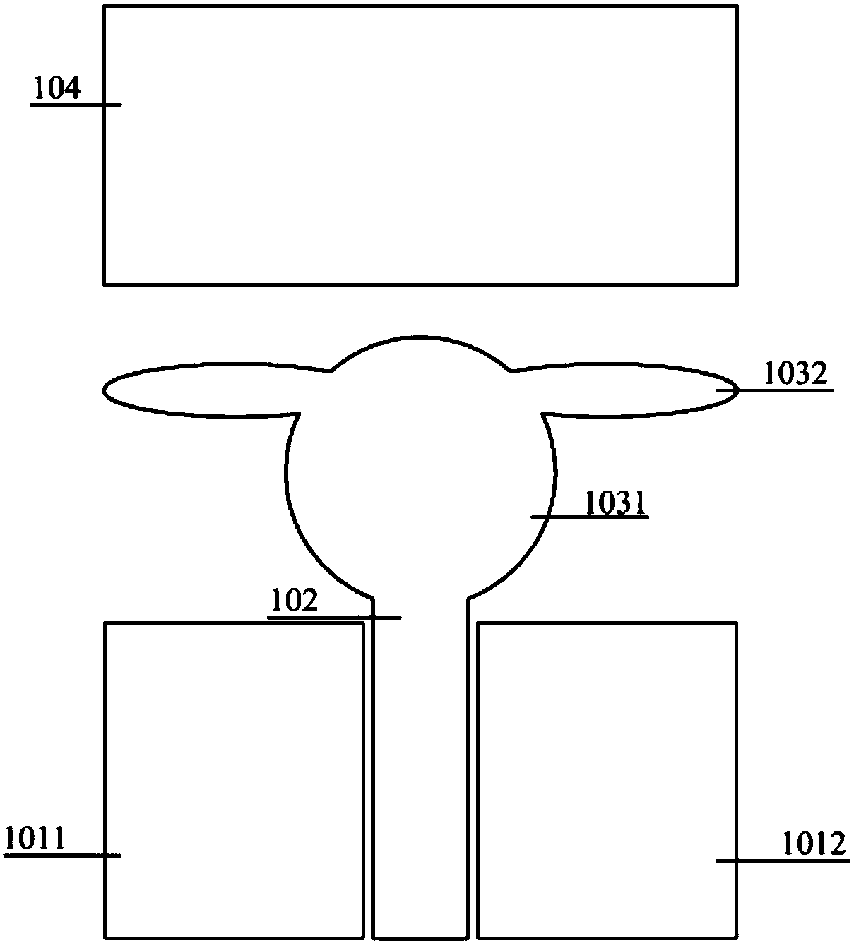
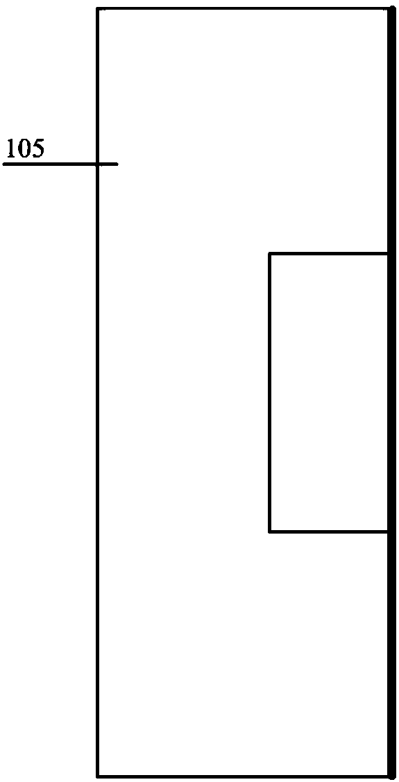
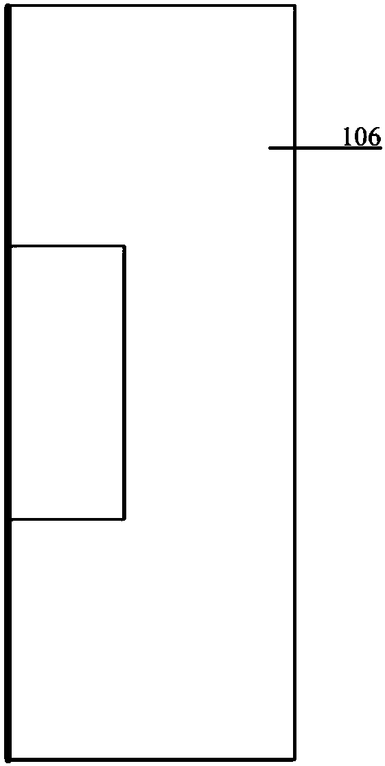
[0029] A broadband directional millimeter-wave antenna of the present invention adopts a rabbit-shaped coupling structure between the main radiation unit and the parasitic radiation unit, and adopts a semi-closed structure composed of a C-shaped reflection surface on a dielectric substrate and a bottom reflection plate on the left and right folding sides. The cavity structure expands the impedance bandwidth of the antenna and realizes the broadband and directional design of the antenna; the left and right folded sides are provided with a C-shaped reflective surface on the dielectric substrate, a bottom reflector, a parasitic radiation unit on the top and a ground plate. The closed cavity structure formed between them can effectively suppress the backward radiation of the antenna, make the antenna have better directional characteristics...


PUM


Abstract

The invention provides a broadband directional millimeter-wave antenna, which comprises a first dielectric substrate, a second dielectric substrate, a third dielectric substrate, a coplanar feed transmission line, a first ground plane, a second ground plane, a parasitic element, a first C-shaped reflecting surface, a second C-shaped reflecting surface, a bottom reflecting plate and a rabbit-shapedmain radiating element, wherein the first C-shaped reflecting surface and the second C-shaped reflecting surface arranged on the dielectric substrates on two left and right folded side surfaces and the bottom reflecting plate of the antenna form a closed cavity structure; the coplanar feed transmission line is connected with an inner conductor of a connector; and an outer conductor of the connector is connected with the ground planes. According to the broadband directional millimeter-wave antenna provided by the invention, the broadband and directional millimeter-wave antenna design is achieved by adopting a coplanar line feed structure, a structural design of a closed cavity formed between the folded dielectric substrates and the bottom reflecting plate and the design of a gap coupling structure between the rabbit-shaped main radiating element and the parasitic radiating element.

Description

technical field [0001] The invention relates to an antenna structure, in particular to a broadband directional millimeter wave antenna. Background technique [0002] In recent years, with the rapid development of wireless communication technology and the popularization and use of electronic devices such as mobile phones and computers, people have put forward higher requirements for the quality of wireless communication. Faster transmission speed and better transmission bandwidth, which means that the communication frequency band needs to continuously develop towards broadband and high frequency, which also promotes the research on broadband antennas, while millimeter wave antennas have short wavelengths and fast transmission speeds , Good communication characteristics and other advantages make it enter the field of vision of most people. Traditional millimeter-wave antennas are generally implemented with waveguide structures. Compared with planar patch antennas, waveguide s...

Claims


Application Information

Patent Timeline
Patent Type & Authority Applications(China)
IPC IPC(8): H01Q19/10H01Q1/36H01Q1/48H01Q1/50H01Q1/22H01Q1/24
CPCH01Q1/2258H01Q1/242H01Q1/36H01Q1/48H01Q1/50H01Q19/106
Inventor 李迎松董玥赵宇婷
Owner HARBIN ENG UNIV
Why Eureka
Try Eureka