A Broadband Microstrip Array Antenna Using Waveguide Feed

A microstrip array and waveguide feeding technology, applied in the field of antennas, can solve the problems of narrow bandwidth and limited applications, and achieve the effects of improved antenna efficiency, simple manufacture, and good symmetry

Active Publication Date: 2020-06-05
NANJING UNIV OF SCI & TECH
View PDF12 Cites 0 Cited by
  • Summary
  • Abstract
  • Description
  • Claims
  • Application Information

AI Technical Summary

Problems solved by technology

However, its narrow bandwidth limits its application in many occasions

Method used


Image

  • A Broadband Microstrip Array Antenna Using Waveguide Feed
  • A Broadband Microstrip Array Antenna Using Waveguide Feed
  • A Broadband Microstrip Array Antenna Using Waveguide Feed

Examples


Embodiment 1

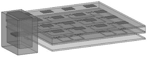
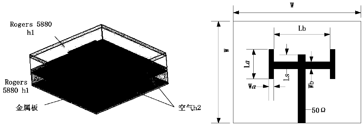
[0032] Such as figure 1 As shown, this embodiment provides a broadband microstrip array antenna fed by a waveguide, including a first dielectric substrate, a second dielectric substrate, a rectangular waveguide and a metal reflector, the first dielectric substrate, the second dielectric substrate And the metal reflectors are arranged sequentially from top to bottom, and an air isolation layer is arranged between two adjacent layers. The upper surface of the first dielectric substrate is provided with a total of 16 sub-radiation units of 4*4, and the upper surface of the second dielectric substrate is It is a metal grounding plate, with 16 H-shaped slots in the same direction, and the center of the H-shaped slot corresponds to the center of the above-mentioned sub-radiation unit one by one, and the lower surface of the second dielectric substrate is provided with a power splitter corresponding to the sub-radiation unit. Electrical network, the microstrip line at the output end ...


PUM

PropertyMeasurementUnit
thicknessaaaaaaaaaa
thicknessaaaaaaaaaa
lengthaaaaaaaaaa

Abstract

Disclosed is a broadband microstrip array antenna adopting waveguide feeding. The broadband microstrip array antenna comprises a first dielectric substrate, a second dielectric substrate, a rectangular waveguide and a metal reflection plate, wherein the first dielectric substrate, the second dielectric substrate and the metal reflection plate are sequentially arranged from top to bottom, and an air isolation layer is arranged between every two adjacent layers; 4*4 sub-radiation units with the number of 16 in total are arranged on the upper surface of the first dielectric substrate; a metal grounding plate, which has 16 H-shaped gaps of the same direction, is arranged on the upper surface of the second dielectric substrate; the centers of the H-shaped gaps correspond to the centers of the sub-radiation units in a one-to-one correspondence mode; an excitation part is located on the side surface of the substrate, and is inserted into the waveguide through a probe, so that feeding is performed based on waveguide. The sub-radiation units disclosed by the invention adopt rectangular patches, so that quite high symmetry is achieved, and the antenna is simple to manufacture.

Description

technical field [0001] The invention belongs to antenna technology, in particular to a wide-band microstrip array antenna using waveguide feeding. Background technique [0002] Compared with traditional antennas, microstrip antennas have many irreplaceable advantages. It is characterized by small size, light weight, low profile, compact structure, and stable performance, and is widely used in radar and communication fields. In 1985, Pozar proposed a microstrip antenna that uses a rectangular slot for coupling feeding. This antenna isolates the radiation layer and the feeding layer through the ground plane, eliminates the mutual influence, and overcomes the traditional feeding method. The inductance effect and the parasitic radiation of the feed network are disadvantages. However, its narrow bandwidth limits its application in many occasions. In order to effectively expand the bandwidth of microstrip antennas, a lot of research has been done at home and abroad, such as the...

Claims


Application Information

Patent Timeline
Patent Type & Authority Patents(China)
IPC IPC(8): H01Q1/36H01Q1/38H01Q1/50H01Q13/08H01Q21/00
CPCH01Q1/36H01Q1/38H01Q1/50H01Q13/08H01Q21/00
Inventor 彭树生李文超吴礼曹迪赵翔张亚曦尚庆龙席光荣高宗彦徐文琪
Owner NANJING UNIV OF SCI & TECH
Why Eureka
Try Eureka