Vibrating Inertial Rate Sensor Utilizing Split or Skewed Operational Elements

a technology of inertial rate and operational elements, applied in the field of angular rate sensors, can solve the problems of affecting the overall uniformity and ability to maintain the desired oscillation mode, the need to regularly compromise the ambition, and the cost and complexity of gyros, so as to improve the rate sense and drive sense signals, improve the resonance performance, and improve the effect of symmetry

Inactive Publication Date: 2007-11-08
WATSON INDUSRIES
View PDF27 Cites 34 Cited by
  • Summary
  • Abstract
  • Description
  • Claims
  • Application Information

AI Technical Summary

Benefits of technology

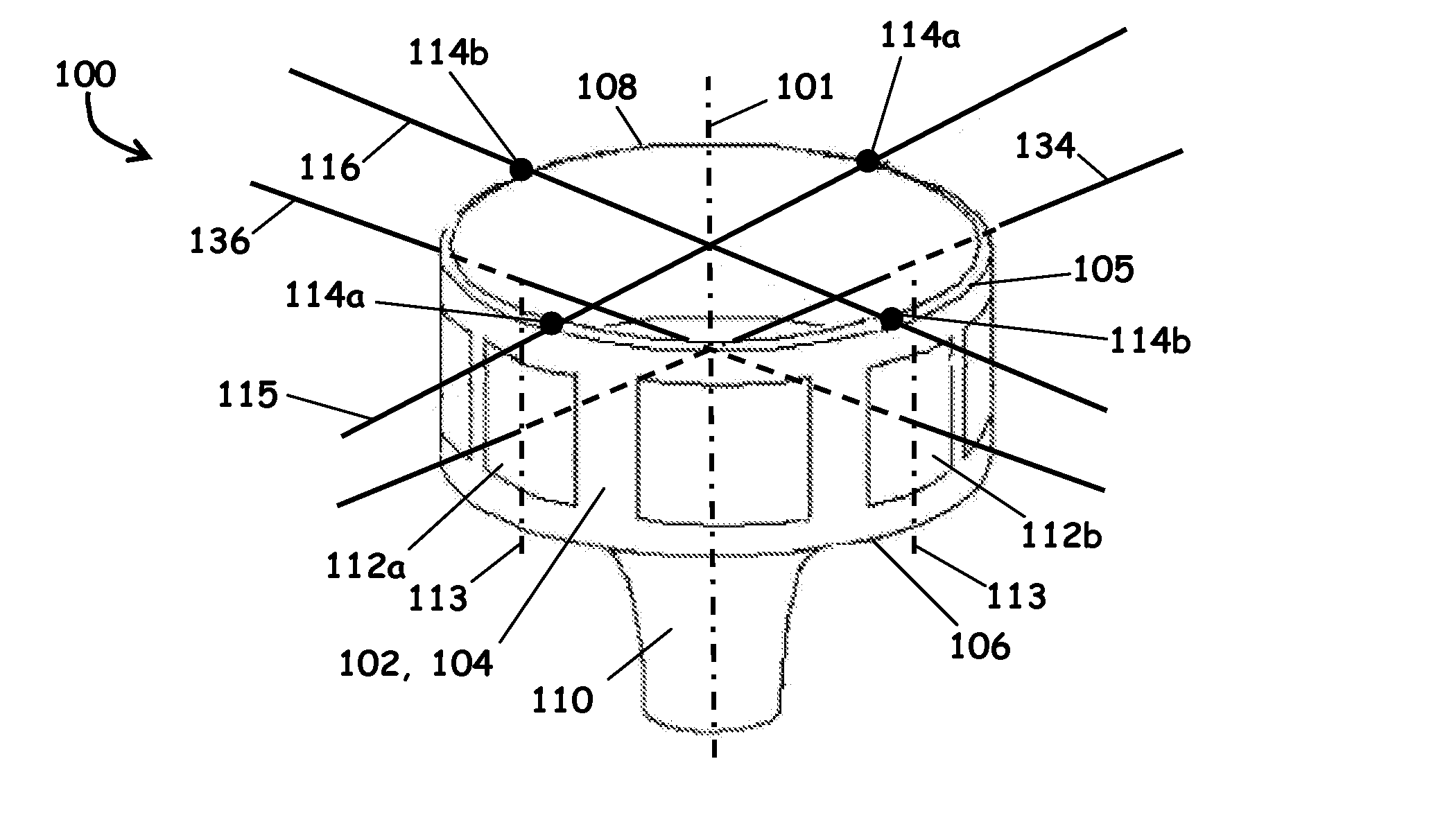
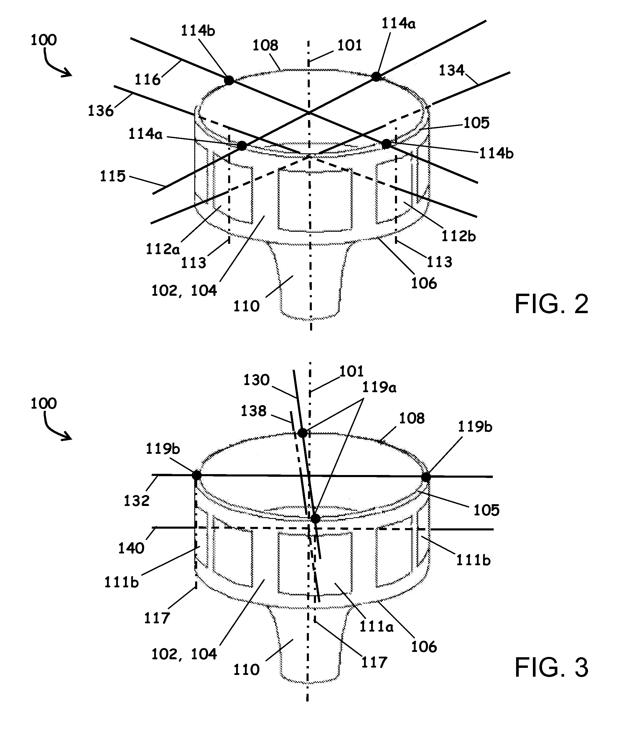
[0027] Advantages of certain skewed and split sense embodiments may include improved rate sense and drive sense signals over existing vibratory gyroscope designs, produced by fewer electrode connections for simplicity and greater symmetry for better resonance performance. Also, the gains of both signals may track and the open loop gain may be constant within the limits of the AGC system because the same electrodes are used for sensing both the rotation rate and the drive amplitude. In addition, the availability of additional sense electrodes may provide for a larger signal-to-noise ratio.
[0028] In another embodiment, a drive element in the form of a pair of drive electrodes may be located substantially opposite one another and rotationally offset from the sense electrodes of the vibratory resonator structure. The drive electrodes serve to control excitation and the subsequent oscillation vector of the vibratory resonator structure. An advantage of the skewed drive electrode configuration is the facilitation of active torquing adjustments through the drive elements without resort to utilizing dedicated elements. The skewed arrangement of the drive elements enables adjustment of the driven oscillation vector without resort to separate, dedicated torque elements. The ratio of the drive voltages for each drive axis is adjusted to affect the position of the drive vector between the two skew angles, thus effecting either static alignment or torquing the drive vector.
[0029] In the skewed drive embodiment, the resonator structure may also define a second node reference axis associated with the desired mode of oscillation, which is substantially orthogonal to the first node reference axis. Because there is no need for a dedicated pair of electrodes to perform the torquing function in this embodiment, a second sense element in the form of a second pair of sense electrodes may be positioned in their stead. The sense electrodes of the second pair are located substantially opposite one another to define a second sense axis that is also rotationally offset or skewed from the second node reference axis. The skew allows a small controlled amount of drive motion to be collected on the electrode along with the rate sense signal. This second pair of sense electrodes generates a second signal of opposite polarity in response to rotation of the inertial sensor apparatus and of the same polarity in response to drive motion. By subtracting the signals from the first and second sense electrodes, one can determine an angular rate sense signal. Addition of the first and second sense electrode signals provides indicia of the drive sense signal.

Problems solved by technology

Unfortunately, these aspirations must be regularly compromised in the real world in order to reduce cost and complexity of the gyros.
In order to maintain symmetry of the oscillation, the mass and size of all of the elements are matched as closely as possible, but the asymmetry introduced by splitting one drive electrode adversely affects the overall uniformity and ability to maintain the desired oscillation mode.
The additional mass of the second connection introduces further asymmetry that is deleterious to resonance performance.
However, these measures tend to add complexity and cost to the design and require extra testing and adjustment.
Even if cost and complexity were not issues, these measures are of limited effectiveness as they attempt to correct the problem after the fact, rather than addressing the underlying challenge.
A detrimental characteristic of these devices is that the automatic gain control (AGC) is disturbed whenever there is a rotation rate present.
The disturbance causes additional noise on the resolved signals.
Moreover, alignment errors between the drive axis and the rate sense axis will overlay the rate sense signal with some amount of drive signal that will create a false indication of rotation.
Although some designs attempt to reduce such undesirable forces by isolating the drive and sense elements, there are still errors that lead to reduced signal-to-noise ratios and false indication of rotation.
While numerous vibration based angular rate sense systems exist, none provide a simple and economical design with the ability to both adjust the angular relationship between the drive and sense elements and maintain symmetrical mass structures for maintaining desired oscillatory modes.
Existing designs also do not accommodate the use of combined functions (i.e. drive and torque or drive sense and rotational sense) in the control and operation of vibration based angular rate sense system.

Method used


Image

  • Vibrating Inertial Rate Sensor Utilizing Split or Skewed Operational Elements
  • Vibrating Inertial Rate Sensor Utilizing Split or Skewed Operational Elements
  • Vibrating Inertial Rate Sensor Utilizing Split or Skewed Operational Elements

Examples


Embodiment Construction

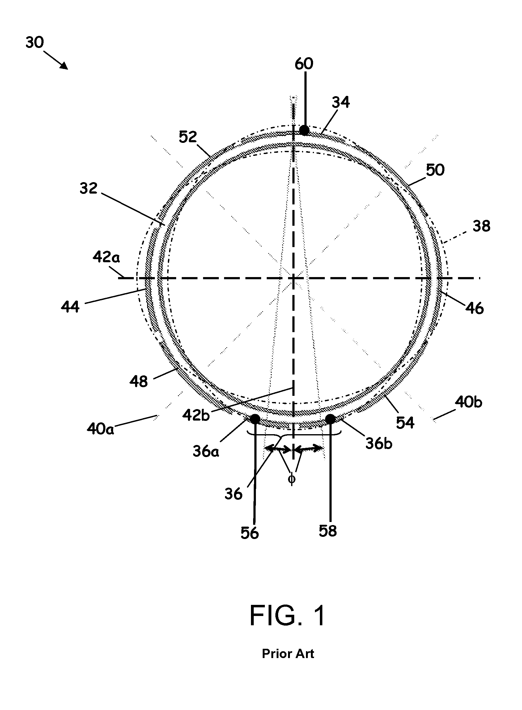
[0067] Referring to FIG. 1, a split drive electrode assembly 30 for correcting undesirable oscillation alignment as is known in the prior art is depicted. The split drive electrode assembly 30 is comprised of a resonator 32 having a generally cylindrical cross-section and features two diametrically opposed drive electrodes 34 and 36, one of which is split into two electrically isolated electrodes 36a and 36b.

[0068] In operation, drive electrode 34 provides a drive signal to generate an oscillation or vibration pattern 38 (shown in phantom) characterized by a pair of node reference axes 40a and 40b, and a pair of anti-node reference axes 42a and 42b. The node reference axes 40a and 40b are defined by the points on the vibration pattern 38 where the amplitudes of the oscillation are at local minima. In contrast, the anti-node reference axes 42a and 42b are defined by the points on the vibration pattern 38 where the amplitudes of the oscillation are at local maxima. Functionally, the ...


PUM


Abstract

A vibrating inertial rate sensor has operational elements that define axes that are rotationally offset or “skewed” from a node or anti-node reference axis. The skew may be relative to separate node or anti-node reference axes, or take the form of an element that is “split” about the same node axis. Both the drive signal and the sense signal may be resolved from a common set of sensing elements. The drive elements may also operate on a skewed axis angle to rotationally offset the vibration pattern to affect active torquing of the gyroscope. Skewed drive elements may be combined with skewed or split elements on the same device. The skewed sensing scheme may be applied to vibratory systems having one or more node axes. The skewed drive scheme may be applied to vibratory systems having two or more node axes to affect active torquing.

Description

RELATED APPLICATIONS [0001] This application is a continuation-in-part of and claims priority to U.S. patent application Ser. No. 11 / 640,823, filed 18 Dec. 2006, which is a continuation in part of U.S. patent application Ser. No. 11 / 379,169, filed 18 Apr. 2006, now abandoned, both of which are hereby incorporated by reference herein in their entirety. This application further claims benefit of the filing date of U.S. Provisional Patent Application No. 60 / 826,046, filed 18 Sep. 2006, which is hereby incorporated by reference herein in its entirety.TECHNICAL FIELD [0002] The present disclosure relates generally to angular rate sensors, and more particularly to vibrating element angular rate sensors used, for example, as gyroscopes. BACKGROUND OF THE DISCLOSURE [0003] Instrumentation sensors that operate on a principle of vibration of constrained actuator masses are known in the art. Angular rate gyroscopes make use of the principle of inertia to measure the rate of rotation through an...

Claims


Application Information

Patent Timeline
Patent Type & Authority Applications(United States)
IPC IPC(8): G01P15/097
CPCG01C19/5691G01C19/56
Inventor WATSON, WILLIAM S.
Owner WATSON INDUSRIES
Why Eureka
Try Eureka