Method for measuring curved surface of workpiece, program and medium thereof

a technology for workpieces and curved surfaces, applied in the direction of mechanical measuring arrangements, instruments, mechanical means, etc., can solve the problems of difficult machining of such curved surfaces of workpieces, difficult to obtain gear pairs showing good tooth bearings, and difficult to achieve both machining and measurement. achieve the effect of easy generation of three-dimensional coordinate values and easy computation

Active Publication Date: 2005-04-21
MITUTOYO CORP
View PDF6 Cites 22 Cited by
  • Summary
  • Abstract
  • Description
  • Claims
  • Application Information

AI Technical Summary

Benefits of technology

[0058] In particular, since, by using the coordinate transformation parameter, it is possible to easily compute the three-dimensional coordinate values and the normal vector at a representative poi

Problems solved by technology

Workpieces that have curved surfaces are of great variety and generally the machining of such curved surface of a workpiece is difficult to do.
However, the tooth flank of such a gear curves in both the tooth trace and tooth depth directions and therefore a problem here is that both the machining and measurement of the gear are difficult to do.
The same is true in the case of a pinion and, if nothing is done, a gear pair showing good tooth bearing can not always be obtained due to the mechanical errors and the like of a gear generator.
However, in such a method for estimating machine setting parameters, though it is necessary to obtain measured tooth flank data M by measuring the data at many points on the tooth flank by way of coordinate measuring, a part program cannot be generated due to the fact that the workpiece tooth flank expression in the workpiece coordinate system is unknown, therefore manual measurem

Method used


Image

  • Method for measuring curved surface of workpiece, program and medium thereof
  • Method for measuring curved surface of workpiece, program and medium thereof
  • Method for measuring curved surface of workpiece, program and medium thereof

Examples


embodiment 1

[Embodiment 1]

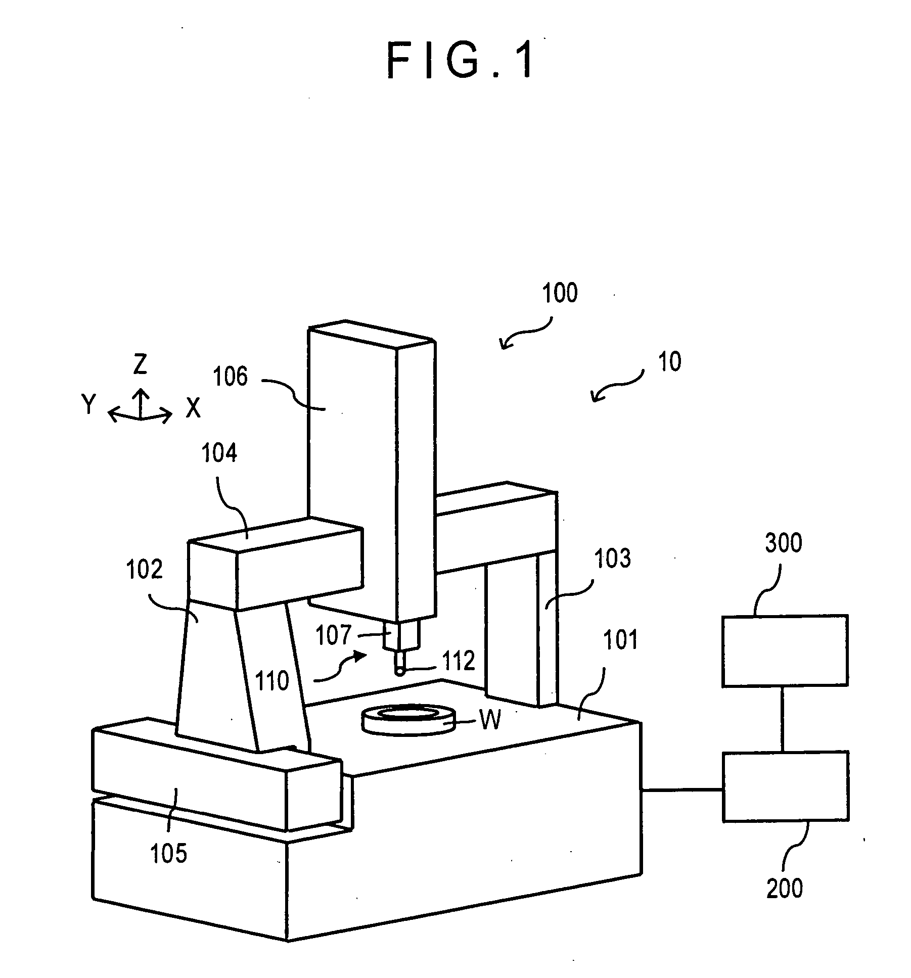
[0085]FIG. 1 shows a first embodiment of a method for measuring a curved surface of a workpiece by using a coordinate measuring machine according to the present invention and a measurement system 10 is composed of the coordinate measuring machine 100, a controller 200 a the computer 300.

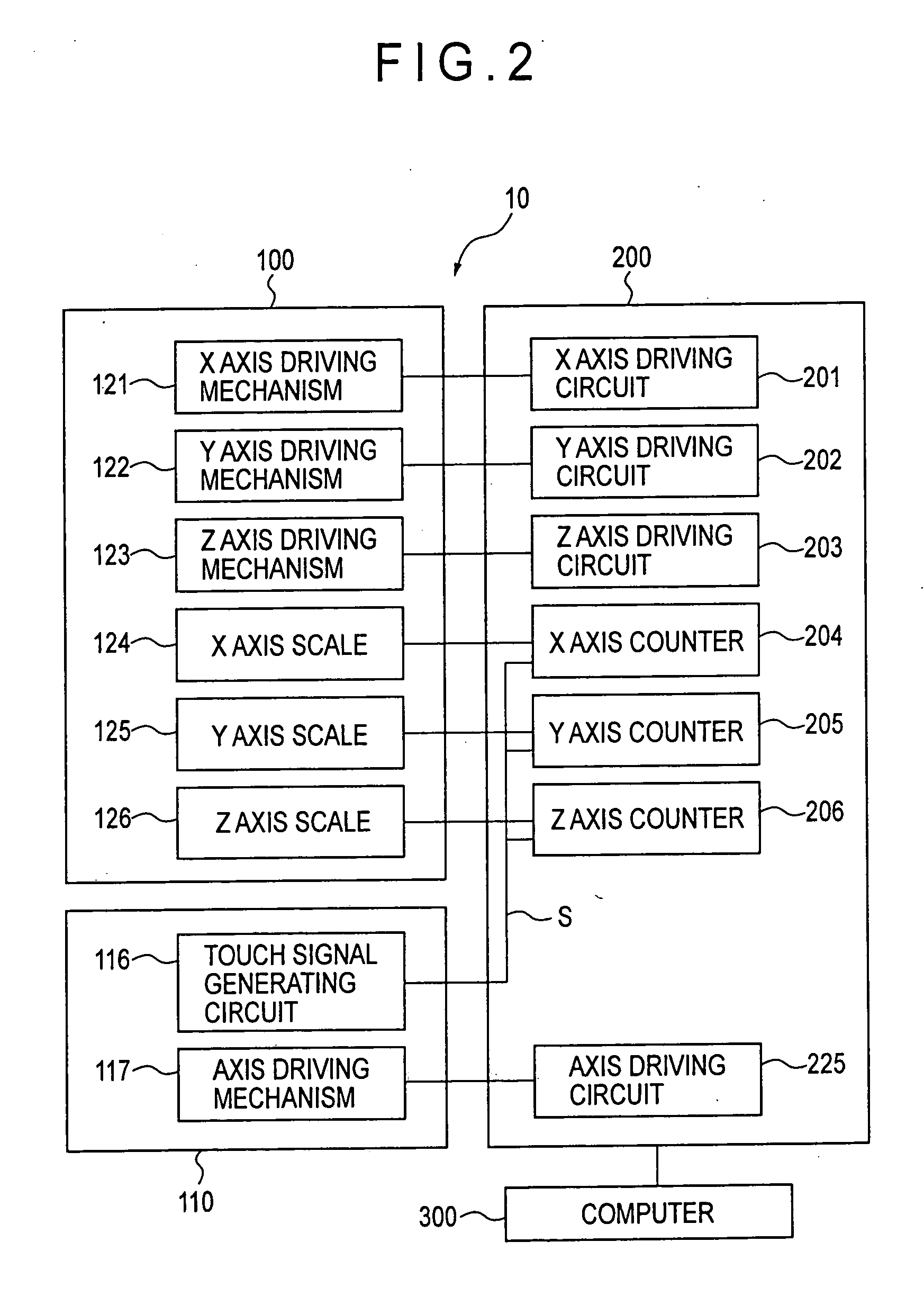
[0086] The coordinate measuring machine 100 is equipped with an X axis beam 104 spanned across a column 102 and a supporter 103, those being placed at both ends of a measurement table 101. Further, it is equipped with an X axis slider 106 (X axis transfer mechanism) that is supported by the X axis beam 104 via air bearings and movable in the X axis direction and a Z axis spindle 107 (Z axis transfer mechanism) that is supported by the X axis slider 106 via air bearings and movable in the Z axis direction. The column 102 and the supporter 103 are also supported afloat by the measurement table 101 via air bearings. The column 102 is guided in the Y axis direction by a Y axis guide mechan...

embodiment 2

[Embodiment 2]

[0141] Embodiment 2 is the case where the computer 300 of Embodiment 1 is replaced with a computer 400 and other configurations thereof are the same as Embodiment 1.

[0142]FIG. 17 shows the block diagram of the computer 400.

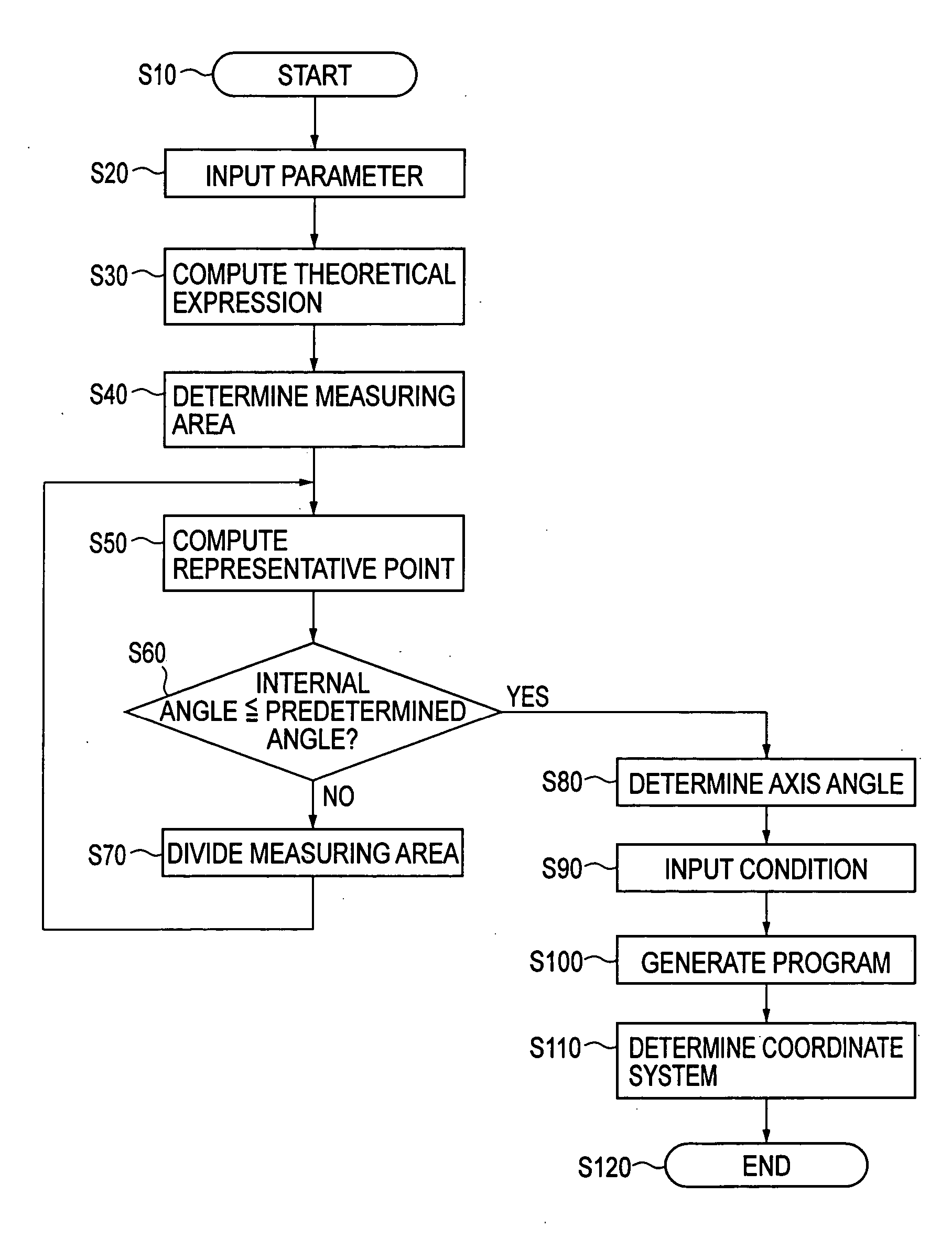
[0143] In FIG. 17, the contents of the operations of a parameter input circuit 401 are identical to those of S20 in FIG. 4, those of a theoretical expression computation circuit 402 identical to those of S30 in FIG. 4, those of a measuring area determination circuit 403 identical to those of S40 in FIG. 4, those of a representative point computation circuit 404 identical to those of S50 in FIG. 4, those of an internal angle judgment circuit 405 identical to those of S60 in FIG. 4, those of a measuring area division circuit 406 identical to those of S70 in FIG. 4, those of an axis angle determination circuit 407 identical to those of S80 in FIG. 4, those of a condition input circuit 408 identical to those of S90 in FIG. 4, those of a program generat...


PUM


Abstract

A theoretical expression of a workpiece (W) the curved surface of which is measured by a measuring probe (110) equipped with a stylus (111) is specified, a measuring area where the measurement is executed on the measuring surface of the workpiece (W) is determined, and the axis angles of the stylus (111) are determined based on the coordinate values and the normal vector of a representative point determined in the measuring area.

Description

BACKGROUND OF THE INVENTION [0001] 1. Field of the Invention [0002] The present invention relates to a method for measuring a curved surface of a workpiece, particularly to a method for measuring a curved surface of a workpiece so as to avoid the interference between the workpiece and a measuring probe. [0003] 2. Description of Related Art [0004] Workpieces that have curved surfaces are of great variety and generally the machining of such curved surface of a workpiece is difficult to do. Therefore, the measurement of a curved surface of a workpiece with a high degree of accuracy is strongly demanded. [0005] A gear is cited as a representative example of a workpiece having such a curved surface and, particularly in the final speed reducer of an automobile or the like, gears such as spiral bevel gears and hypoid gears having tooth flanks of curved surfaces are frequently used as gears to change the direction of a rotation axis and reduce the speed in the transmission of rotation power...

Claims


Application Information

Patent Timeline
IPC IPC(8): G01B21/04
CPCG01B21/04
Inventor NOMURA, YOICHIMICHIWAKI, HIROKAZU
Owner MITUTOYO CORP
Why Eureka
Try Eureka