Axis angle determination method for six-axis robot and control apparatus for six-axis robot

a technology of axis angle determination and control apparatus, which is applied in the direction of programmed manipulators, instruments, programme control, etc., can solve the problems of increased user work load, and increased error processing, so as to prevent the increase of user work load, the effect of increasing the work load and increasing the user's work load

Active Publication Date: 2015-04-30
DENSO WAVE INC
View PDF0 Cites 20 Cited by
  • Summary
  • Abstract
  • Description
  • Claims
  • Application Information

AI Technical Summary

Benefits of technology

[0012]In the axis angle determination method for a six-axis robot of the present invention, the first axis to third axis of the six-axis robot may be configured by linear-motion axes that are perpendicular to one another. In a six-axis robot configured in this way, the first axis to third axis respectively correspond to three-dimensional coordinates X, Y and Z. The fourth axis to sixth axis are moved in the directions of the coordinate axes. Under a presumption that the six-axis robot is made to perform an operation such as pick-and-place, the six-axis robot often takes an attitude in which the approach vector of the hand indicates the negative direction of the Z axis, and the rotation axes of the fourth axis and the sixth axis match. If this attitude is handled by error processing as in conventional technology, error processing frequently occurs. The work load on the user increases. Therefore, when the six-axis robot configured as described above is the subject, the increase in work load on the user can be prevented. The invention of the present application is very

Problems solved by technology

As a result, work load on the user also increases.
If this attitude is handled by error processing as

Method used


Image

  • Axis angle determination method for six-axis robot and control apparatus for six-axis robot
  • Axis angle determination method for six-axis robot and control apparatus for six-axis robot
  • Axis angle determination method for six-axis robot and control apparatus for six-axis robot

Examples


first embodiment

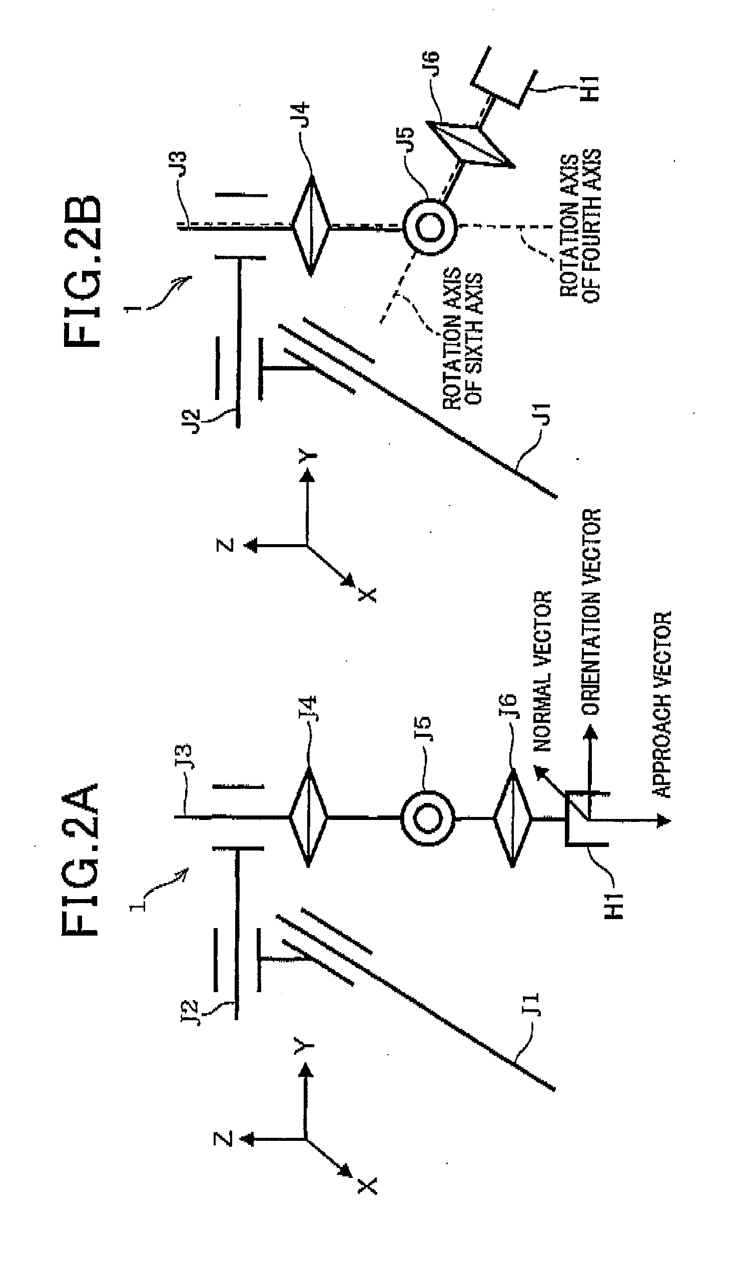
[0021]A first embodiment will hereinafter be described with reference to FIGS. 1 to 4. FIG. 3 is a perspective view of a configuration of a six-axis robot. A robot 1 has a first axis J1, a second axis J2, a third axis J3, a fourth axis J4, a fourth axis J5, and a sixth axis J6. Of the axes J1 to J6, the first axis J1, the second axis J2, and the third axis J3 are configured by linear-motion axes that are perpendicular to each other.

[0022]The first axis J1 is disposed along the X-axis direction in FIG. 3. The first axis J1 is provided with a ball screw therein (not shown). The first axis J1 also has a nut (not shown). A driving motor 20(1) (see FIG. 4) rotates the ball screw, thereby fastening the nut to the ball screw. A movable body 2 is disposed on the top surface side of the first axis J1. When the driving motor 20(1) rotates the ball screw, the movable body 2 moves linearly along the first axis J1.

[0023]The second axis J2 is disposed along the Y-axis direction in FIG. 3. One end...

second embodiment

[0052]FIG. 5 shows a second embodiment. Sections that are the same as those according to the first embodiment are given the same reference numbers. Descriptions thereof will be omitted. Differences will be described below.

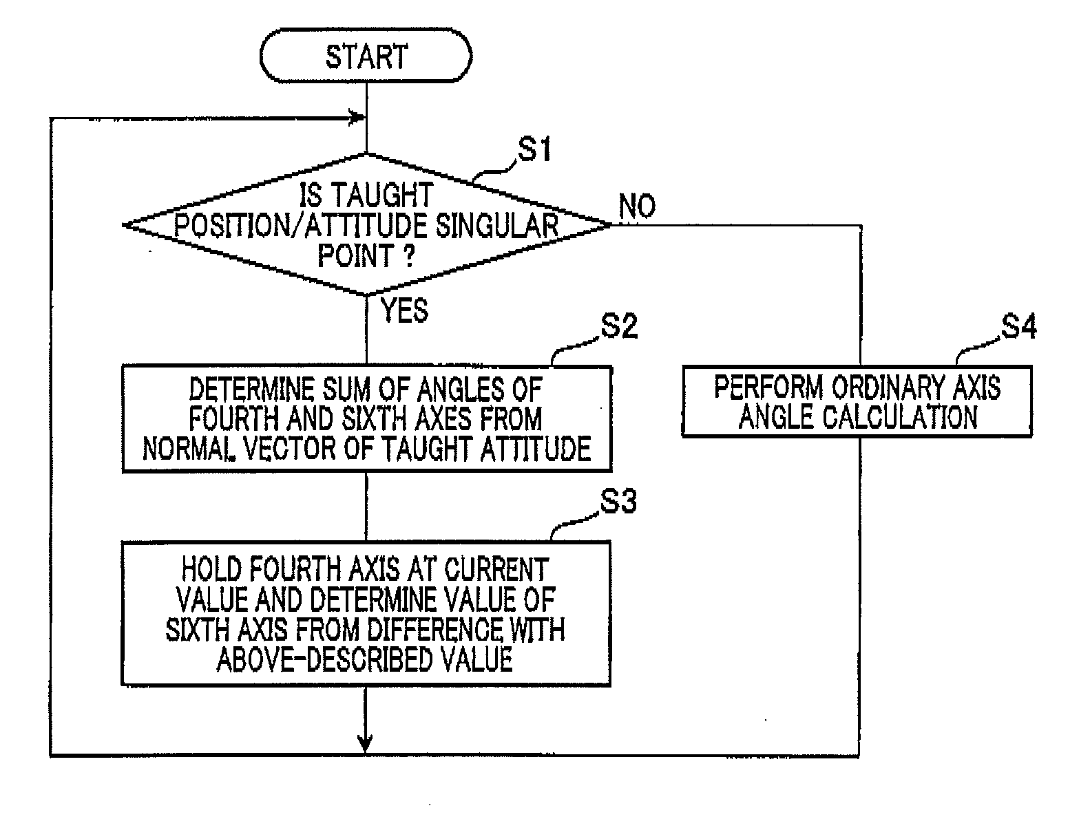
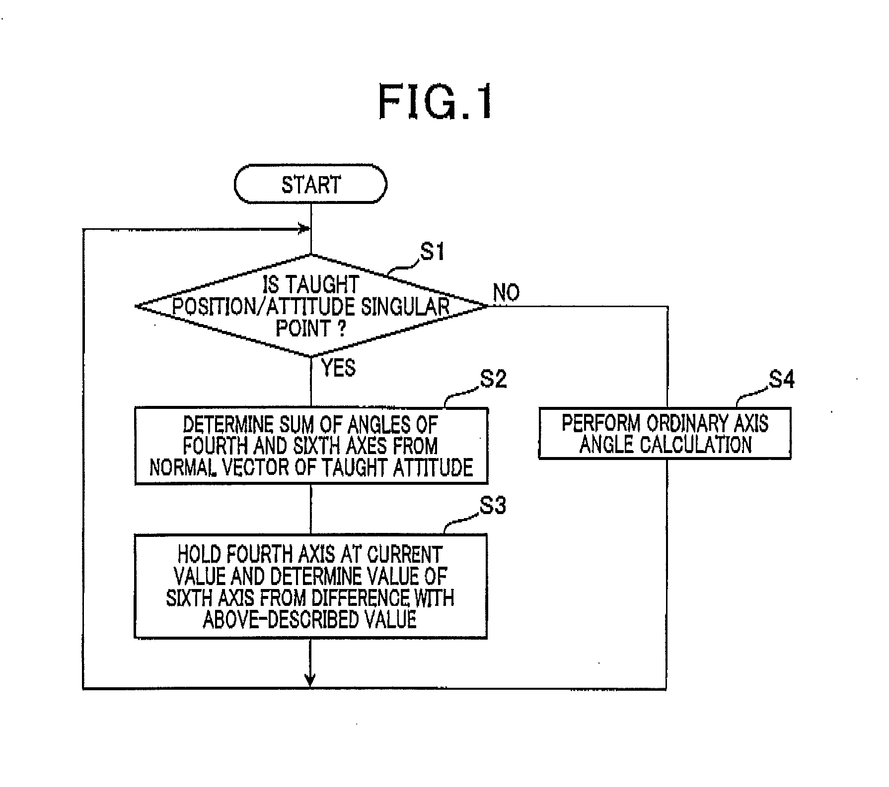
[0053]As shown in FIG. 5, according to the second embodiment, when determined “YES” at step S1, the controller 10 determines the sum θ4+6 of the angles at subsequent Step S11, in a manner similar to that at step S2. In addition, the controller 10 determines a movement amount δθ from the current values of the angles. The movement amount δθ herein is equivalent to the “difference” between the angles determined at step S3 according to the first embodiment.

[0054]At subsequent step S12, the controller 10 determines time T4 and time T6 based on the respective rotation speeds of the fourth axis J4 and the sixth axis J6. The time T4 is when the fourth axis J4 is rotated by the movement amount δθ. The time T6 is when the sixth axis J6 is rotated by the movement amount δθ. I...


PUM


Abstract

In an axis angle determination method, an angle or a position of each axis of a six-axis robot is determined. The robot is capable of taking an attitude of a singular point being a state in which rotation axes of fourth and sixth axes match. Based on teaching results of a position and attitude of a hand by point-to-point teaching, the method judges whether an attitude of the robot in which the angle or the position of each angle is to be determined next is a singular point. If judged that the attitude is the singular point, angles of the fourth and sixth axes required for the six-axis robot to move to the singular point are determined such that an angle of one of the fourth and sixth axes is fixed to a current value and an angle of the other axis is determined based on the fixed angle.

Description

CROSS-REFERENCE TO RELATED APPLICATION[0001]This application is based on and claims the benefit of priority from Japanese Patent Application No. 2013-225423, filed Oct. 30, 2013, the disclosure of which is incorporated herein in its entirety by reference.BACKGROUND[0002]1. Technical Field[0003]The present invention relates to a method and an apparatus for determining an angle of each axis of a six-axis robot based on a result of teaching of a position and an attitude (position / attitude) of a hand of the six-axis robot through teaching.[0004]2. Related Art[0005]A six-axis robot includes first to sixth axes, and is capable of taking an attitude (posture) in which a rotation axis of the fourth axis and a rotation axis of the sixth axis robot match.[0006]For example, in a perpendicular articulated six-axis robot, the rotation axes of a fourth axis and a sixth axis of the six-axis robot match when the six-axis robot takes an attitude (posture) in which a hand of the six-axis robot faces ...

Claims


Application Information

Patent Timeline
IPC IPC(8): B25J9/16G05B19/402
CPCB25J9/1664B25J9/163Y10S901/14G05B2219/39298Y10S901/04G05B19/402G05B2219/40562
Inventor IDE, SATOSHIKAGAWA, NAOYAKAWASE, DAISUKE
Owner DENSO WAVE INC
Why Eureka
Try Eureka