Supercharge Your Innovation With Domain-Expert AI Agents!

Gear motor and pointer-type display device

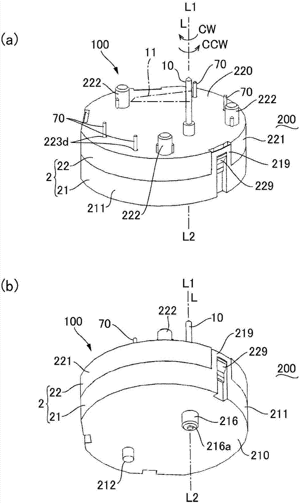
A technology of gear motors and gears, which is applied in the direction of electromechanical devices, mechanical energy control, electrical components, etc., and can solve problems such as the inability of the gear to rotate, the deformation of the convex part on the side of the gear or the convex part on the side of the support body, and the inability to reassemble, etc.

Inactive Publication Date: 2017-11-21
SANKYO SEIKI MFG CO LTD
View PDF6 Cites 0 Cited by
  • Summary
  • Abstract
  • Description
  • Claims
  • Application Information

AI Technical Summary

Problems solved by technology

Even in this case, the lower case and the upper case can be coupled by simply pressing the upper case, but the gear side convex part and the support body side convex part contact in the direction of the rotation center axis, and the gear cannot rotate. The problem
In addition, when the upper case is pressed, the plate-shaped portion of the gear, the end plate portion of the support member, the gear-side convex portion, or the support body-side convex portion may be deformed. In this case, reassembly cannot be performed.

Method used


Image

  • Gear motor and pointer-type display device
  • Gear motor and pointer-type display device
  • Gear motor and pointer-type display device

Examples


Deformed example 1

[0112] Figure 7 It is an explanatory diagram of the driven side gear 42 used in the gear motor 100 according to Modification 1 of the present invention. In addition, since the basic structure of this example and the modification 2 mentioned later is the same as that of the said embodiment, the same code|symbol is attached|subjected to a common part, and their description is abbreviate|omitted. In the above-mentioned embodiment, the gear-side convex portion 48 for the stopper mechanism 9 is integrated with the interfered portion 49, but as Figure 7 As shown, the gear-side convex portion 48 and the interfered portion 49 may be constituted by each of two convex portions separated in the rotation center axis L direction.

Deformed example 2

[0114] Figure 8 It is an explanatory diagram of the driven side gear 42 used in the gear motor 100 according to Modification 2 of the present invention. In the above-described embodiment, the configuration is such that the first case member 21 and the second case member 22 are overlapped in a state where the gear-side protrusion 48 and the support body-side protrusion 28 overlap each other in the rotation center axis L direction. At this time, the interfering portion 29 abuts against the interfered portion 49 to separate the hook 219 (joint portion) of the first case member 21 from the engaging convex portion 229 (joint portion) provided on the second case member 22, but In the present embodiment, the interfered portion 49 is a slope inclined in the circumferential direction. Furthermore, the interfering portion 29 (not shown) is an inclined surface inclined in a direction opposite to the interfered portion 49 . Therefore, when the first housing member 21 and the second hou...


PUM


Abstract

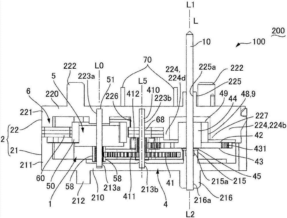
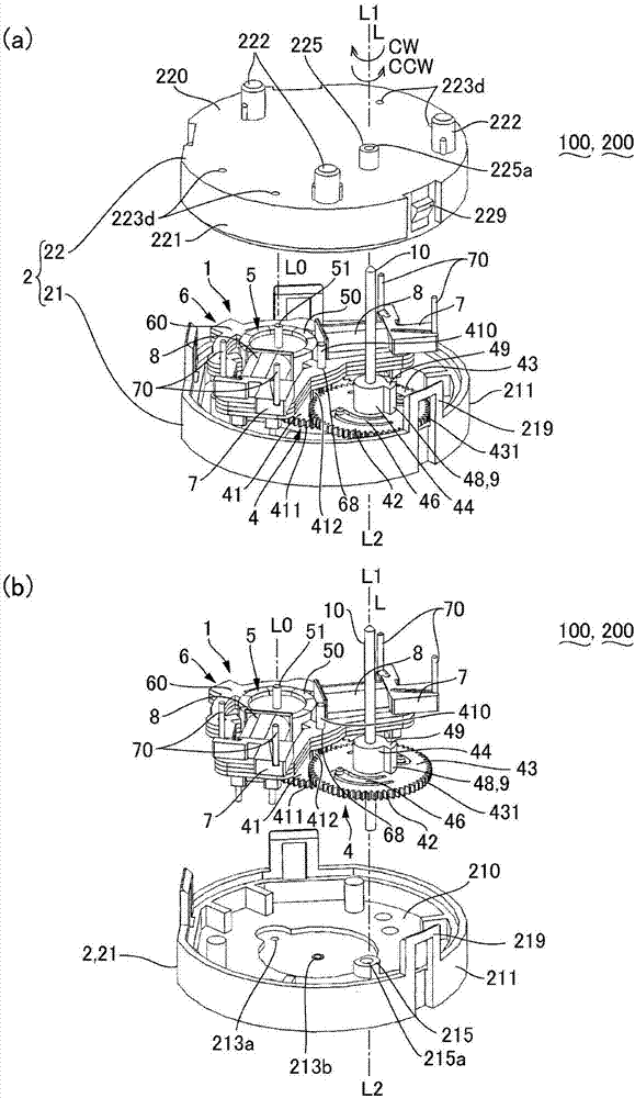
The invention provides a gear motor and a pointer-type display device. Even if a stop mechanism is arranged between a gear and a supporting part, the case that the gear is assembled in a state that the gear is unable to rotate can be prevented. In the gear motor (100), a driven side gear (42) is provided with a stopping gear side protrusion (48) which protrudes from a plate-type part (43) towards a second housing part (22). The second housing part (22) is provided with a stopping supporting part side protrusion which protrudes towards the plate-type part (43) and abuts against the gear side protrusion (48) in the circumferential direction. The driven side gear (42) is provided with an interfered part (49), under the condition that the gear side protrusion (48) and the supporting part side protrusion are overlapped in the rotating central axis (L), when a first housing part (21) and the second housing part (22) are overlapped, the interfered part (49) abuts against an interfering part arranged on the second housing part (22) in the rotating central axis (L) to prevent the combination of a hook (219) and a clamping protrusion (229).

Description

technical field [0001] The invention relates to a gear motor and a pointer display device provided with a stopper mechanism in a gear train. Background technique [0002] In pointer display devices and the like, a gear motor having a motor and a gear train inside a casing is used, and a pointer is fixed to an output member of the gear motor (Patent Document 1). Patent Document 1 proposes a technique in which a stopper mechanism for stopping a gear at a predetermined position is provided with respect to the gear motor. More specifically, a structure has been proposed in which, in the gear, a stopper gear-side convex portion protruding toward the support member is provided on a plate-shaped portion formed with teeth on the outer peripheral surface, and a stopper is provided on the end plate portion of the support member. The support body-side protrusion for a stopper protrudes toward the plate-shaped portion, and the support body-side protrusion abuts against the gear-side pr...

Claims


Application Information

Patent Timeline
Patent Type & Authority Applications(China)
IPC IPC(8): H02K7/116
CPCH02K7/116
Inventor 保科哲夫横山正树一濑惣真
Owner SANKYO SEIKI MFG CO LTD
Features
  • R&D
  • Intellectual Property
  • Life Sciences
  • Materials
  • Tech Scout
  • Unparalleled Data Quality
  • Higher Quality Content
  • 60% Fewer Hallucinations
Learn More