
A method of improving sealing performance of butterfly valve and structure of high-sealing butterfly valve

A high-sealing, butterfly valve technology, applied in shaft seals, lift valves, valve details, etc., can solve problems affecting the normal use of butterfly valves, poor sealing performance, and reduced sealing performance of butterfly valves, so as to ensure sealing performance, improve sealing performance, and improve Effect of Shaft End Sealing Performance

Active Publication Date: 2018-07-24
ZHEJIANG WEI KENTE PUMP
View PDF6 Cites 0 Cited by
  • Summary
  • Abstract
  • Description
  • Claims
  • Application Information

AI Technical Summary

Problems solved by technology

However, the existing butterfly valves are generally sealed with rubber rings or metal rings. After a long period of use, the sealing performance of the butterfly valve will be reduced, which will affect the normal use of the butterfly valve.
Therefore, the prior art has the problem of poor sealing performance

Method used


Image

  • A method of improving sealing performance of butterfly valve and structure of high-sealing butterfly valve
  • A method of improving sealing performance of butterfly valve and structure of high-sealing butterfly valve
  • A method of improving sealing performance of butterfly valve and structure of high-sealing butterfly valve

Examples


Embodiment Construction

[0024] The present invention will be further described below in conjunction with the accompanying drawings and embodiments, but it is not used as a basis for limiting the present invention.

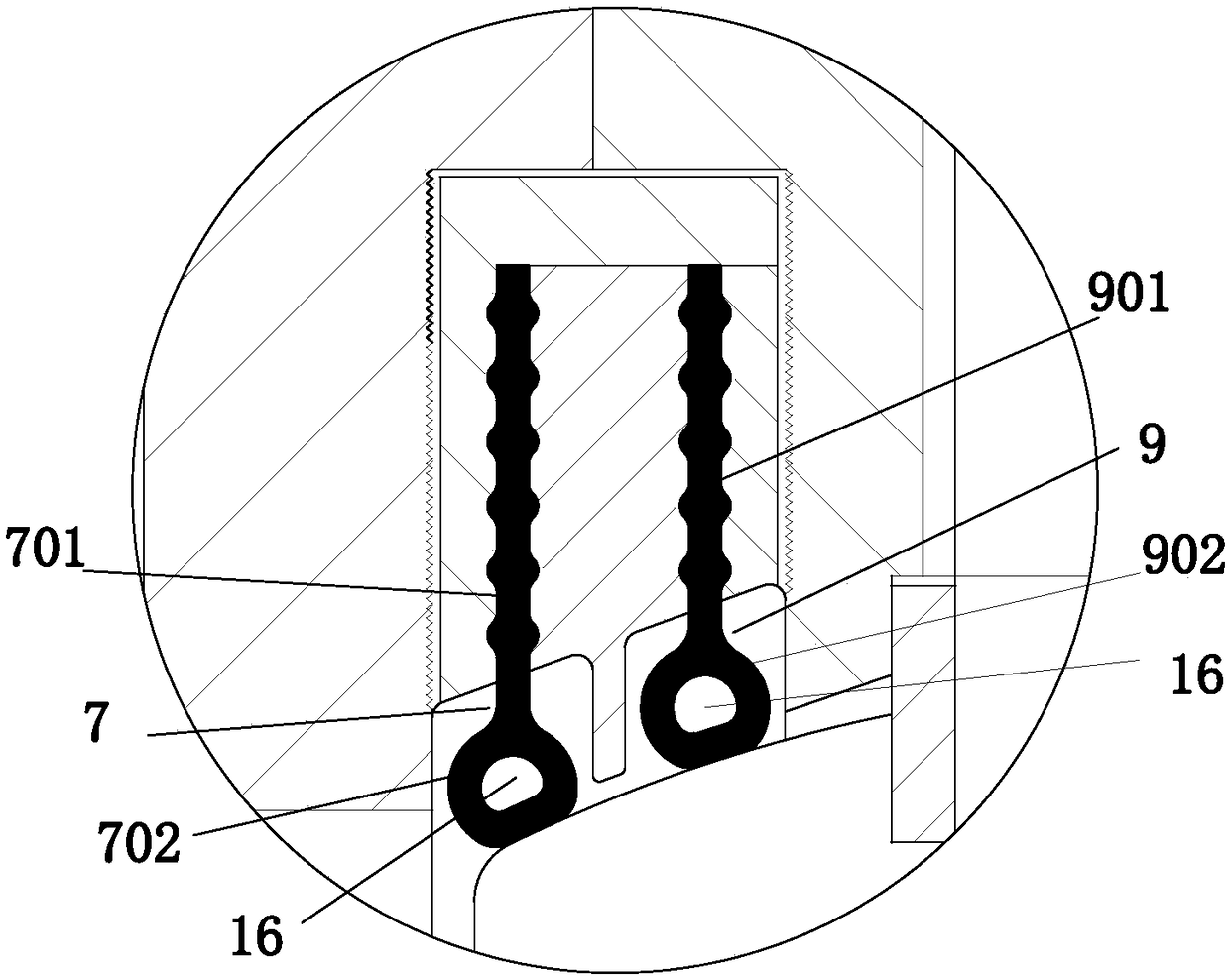
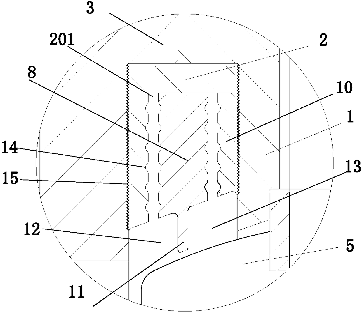
[0025] Example. A method for improving the sealing performance of a butterfly valve. A butterfly valve sealing device is arranged between a valve seat and a valve body to seal and cooperate with a valve clack; a shaft sealing device is arranged on the valve body to seal with a valve stem.

[0026] The butterfly valve sealing device divides the valve cover and the valve body into two mutually independent first sealing chambers and second sealing chambers through the partition plate, and sets the first sealing chamber between the valve cover and the valve body respectively. The first sealing ring and the second sealing ring corresponding to the chamber and the second sealing chamber serve the purpose of double sealing.

[0027] The shaft sealing device squeezes the sealing packing into a V...


PUM


Abstract

The invention discloses a method for improving the sealing performance of a butterfly valve and a high-sealing butterfly valve structure. Two symmetrically-arranged butterfly valve sealing devices are arranged between a valve seat and a valve body and are in sealing fit with a valve clack. A shaft sealing device is arranged on the valve body, and the shaft sealing device and a valve rod achieve sealing. The structure comprises the valve body. The valve seat and a valve cover are arranged on the outer side of the valve body, the valve rod and the valve clack are arranged in the valve body, and the shaft sealing device is arranged at the upper end of the valve body. Two sets of symmetrically-arranged valve clack sealing devices are arranged between the valve seat and the valve body. Each valve clack sealing device comprises a first sealing ring, a valve seat middle partition plate, a second sealing ring and a valve seat cover plate. A splitter plate is annularly arranged in each valve seat middle partition plate. A first sealing cavity is formed between each splitter plate and the valve cover and corresponds to the corresponding first sealing ring. A second sealing cavity is formed between each splitter plate and the valve body and corresponds to the corresponding second sealing ring. The method and the structure have the beneficial effect of being capable of improving the sealing performance of the butterfly valve.

Description

technical field [0001] The invention relates to a butterfly valve, in particular to a method for improving the sealing performance of the butterfly valve and a high-sealing butterfly valve structure. Background technique [0002] Butterfly valve, also known as flap valve, is a regulating valve with simple structure, which can be used for switch control of low-pressure pipeline medium. Butterfly valve refers to a valve whose closing part (disc or butterfly plate) is a disc that rotates around the valve stem to open and close. The valve can be used to control air, water, steam, various corrosive media, mud, oil , liquid metal and radioactive medium and other types of fluid flow. The advantages of the butterfly valve are mainly manifested in the convenient and rapid opening and closing, labor saving, small fluid resistance, and frequent operation; Less effort. However, the existing butterfly valves are generally sealed with rubber rings or metal rings. After a long period of...

Claims


Application Information

Patent Timeline
Patent Type & Authority Patents(China)
IPC IPC(8): F16K1/226F16K1/42F16K41/02
CPCF16K1/226F16K1/2263F16K1/2268F16K1/42
Inventor 徐金雷陈向军刘婷婷张小乾陈显忠张日鹏
Owner ZHEJIANG WEI KENTE PUMP
Learn More