
An Improved Transformer Winding Frame Structure

A winding frame and transformer technology, which is applied in the field of transformers, can solve problems such as wire coil distortion, and achieve the effects of improving uniformity, improving heat dissipation uniformity, and improving support coordination

Active Publication Date: 2018-12-18
山东永锦电气股份有限公司
View PDF6 Cites 0 Cited by
  • Summary
  • Abstract
  • Description
  • Claims
  • Application Information

AI Technical Summary

Problems solved by technology

Under the influence of this long-term temperature fluctuation, the wire coil wound on the winding frame will be deformed due to its own thermal expansion and contraction. When the heating conditions of different parts of the coil are different, irregular deformation will occur, which is easy Causes excessive twisting of wire coils

Method used


Image

  • An Improved Transformer Winding Frame Structure
  • An Improved Transformer Winding Frame Structure
  • An Improved Transformer Winding Frame Structure

Examples


Embodiment Construction

[0019] The standard parts used in the present invention can be purchased from the market, and the special-shaped parts can be customized according to the instructions and the accompanying drawings. The specific connection methods of each part adopt mature bolts, rivets, welding in the prior art , pasting and other conventional means, no longer described in detail here.

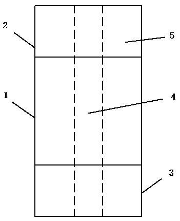
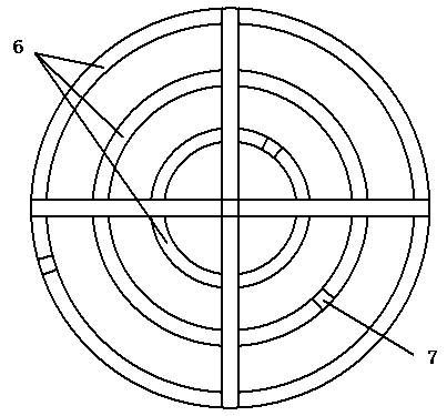
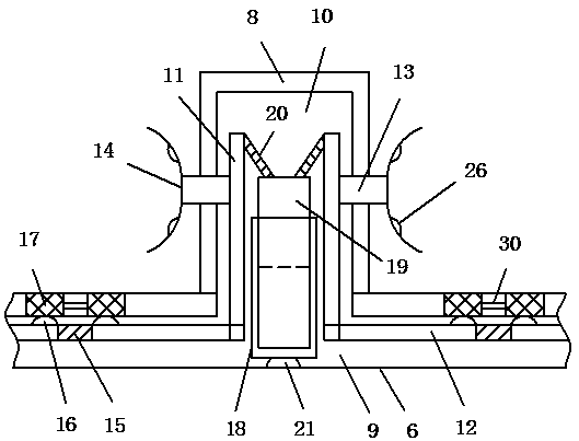
[0020] refer to Figure 1-5 , a specific embodiment of the present invention includes a frame body 1, the two ends of the frame body 1 are the primary winding winding area 2 and the secondary winding winding area 3 respectively, and the center of the frame body 1 is provided with a first through hole 4, the primary The winding winding area 2 and the secondary winding winding area 3 are respectively equipped with wire reels 5. The wire reels 5 include several concentrically arranged annular winding plates 6, and the annular winding plates 6 are provided with second through holes 7. Several baffles 8 are arrang...


PUM


Abstract

The invention discloses an improved transformer winding rack structure. The improved transformer winding rack structure comprises a rack body, wherein a primary winding region and a secondary winding region are respectively arranged at two ends of the rack body, coils are respectively arranged on the primary winding region and the secondary winding region, each coil comprises a plurality of annular winding plates which are concentrically arranged, second through holes are formed in the annular winding plates, a plurality of baffle plates are arranged on the annular winding plates, a first cavity is formed in the annular winding plate between two adjacent baffle plates along an axial direction of the annular winding plate, a second cavity is formed in each baffle plate and communicates with the first cavity, two first support rods are symmetrically arranged in the second cavity and are respectively hinged with second support rods in the first cavities at two sides, third support rods are hinged with side walls of the first support rods, and an arc support plate is fixedly connected with one end, arranged at an outer side of the baffle plate, of each third support rod. By the improved transformer winding rack structure, the defect of the prior art can be improved, and the protection effect of a winding coil is improved.

Description

technical field [0001] The invention relates to the technical field of transformers, in particular to an improved winding frame structure of a transformer. Background technique [0002] The transformer winding frame is the main structural part of the transformer, which provides winding space for the wire coil in the transformer and fixes the iron core in the transformer. During the working process of the transformer, with the change of the transformer load, the temperature fluctuation inside the transformer will also increase. Under the influence of this long-term temperature fluctuation, the wire coil wound on the winding frame will be deformed due to its own thermal expansion and contraction. When the heating conditions of different parts of the coil are different, irregular deformation will occur, which is easy Causes excessive twisting of wire coils. Contents of the invention [0003] The technical problem to be solved by the present invention is to provide an improv...

Claims


Application Information

Patent Timeline
Patent Type & Authority Patents(China)
IPC IPC(8): H01F27/30H01F27/08
CPCH01F27/2876H01F27/306
Inventor 张海江
Owner 山东永锦电气股份有限公司
Learn More