
A plane coiling multi-knife slitting machine

A plane and longitudinal cutting technology, which is applied in the direction of winding strips, metal processing, thin material processing, etc., can solve problems such as deviation, large space occupation, complex structure, etc., to prevent deviation and wrinkles, and ensure cutting effect , a wide range of effects

Active Publication Date: 2016-01-13
TAIXING SHUANGYANG LEATHER RUBBER MACHINERY FACTORY
View PDF7 Cites 0 Cited by
  • Summary
  • Abstract
  • Description
  • Claims
  • Application Information

AI Technical Summary

Problems solved by technology

Such as the tire rubber slitting machine disclosed in Patent No. 200810020292, its technical feature is that it includes three groups of sequentially connected feeding conveyors, slitting mechanisms and discharge conveyors. The cylindrical cutter heads on the shaft are set at intervals; the disadvantages of this technical solution are: (1) The three groups of mechanisms are connected in series in sequence, which takes up a lot of space; (2) Each group of mechanisms is equipped with its own driving mechanism, and the structure is complicated; ( 3) The discharge conveyor rewinds the cut rubber strips. There is no rewinding mechanism for the remaining material, and it cannot realize lane-by-lane rewinding and layered rewinding.
(4) There is no deviation correcting device on the feeding conveyor, which is prone to deviation during the cutting process; (5) The width of rubber cutting is fixed and difficult to adjust, and the distance between the upper and lower cylindrical cutter heads is fixed, and only fixed thickness can be cut rubber

Method used


Image

  • A plane coiling multi-knife slitting machine

Examples


Embodiment Construction

[0018] Below in conjunction with accompanying drawing, the specific embodiment of the present invention is described in further detail:

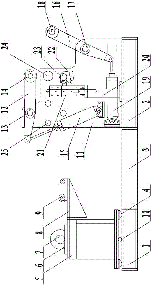
[0019] As shown in the figure, a plane coiling multi-knife slitting machine includes an unwinding mechanism and a main machine, the unwinding base 1 at the bottom of the unwinding mechanism is connected to the main machine base 2 at the bottom of the main machine through a connecting support 3; the main machine includes The host housing 11, the winding mechanism and the rolling cutting mechanism, the rolling cutting mechanism is arranged in the middle of the main engine, the rolling mechanism includes an upper winding mechanism and a lower winding mechanism, and the upper winding mechanism is arranged on the rolling cutting mechanism The upper left of the mechanism, and the lower winding mechanism is arranged at the lower right of the rolling cutting mechanism.

[0020] The unwinding mechanism includes an unwinding base 1, an unwinding slide...


PUM


Abstract

The invention relates to a plane rolling multi-cutter longitudinal cutting machine. The cutting machine comprises an unrolling mechanism and a main engine. A base of the unrolling mechanism is connected with a main engine base through a connecting support. The main engine comprises a main engine shell, the main engine base, a rolling mechanism and a rolling-cutting mechanism. The rolling-cutting mechanism is arranged in the middle of the main engine, the rolling mechanism comprises an upper rolling mechanism and a lower rolling mechanism, the upper rolling mechanism is arranged at the top left of the rolling-cutting mechanism, and the lower rolling mechanism is arranged at the lower right of the rolling-cutting mechanism. An upper rolling air cylinder is hinged to the main engine shell. Due to the facts that the upper rolling mechanism, the lower rolling mechanism and the rolling-cutting mechanism are arranged on the main engine, and an upper rolling shaft, a lower rolling shaft and a rolling-cutting shaft are driven by the same drive mechanism, the structure is simplified, and meanwhile synchronization of cutting and rolling is ensured.

Description

technical field [0001] The invention relates to a rubber cutting machine, in particular to a plane coiling multi-knife slitting machine. Background technique [0002] Plane coiling multi-knife slitting machine is used in the rubber tire industry to cut rubber into strips. Traditional longitudinal machines usually have problems such as large space occupation and easy deviation during cutting. Such as the tire rubber slitting machine disclosed in Patent No. 200810020292, its technical feature is that it includes three groups of sequentially connected feeding conveyors, slitting mechanisms and discharge conveyors. The cylindrical cutter heads on the shaft are set at intervals; the disadvantages of this technical solution are: (1) The three groups of mechanisms are connected in series in sequence, which takes up a lot of space; (2) Each group of mechanisms is equipped with its own driving mechanism, and the structure is complicated; ( 3) The discharge conveyor rewinds the cut ...

Claims


Application Information

Patent Timeline
Patent Type & Authority Patents(China)
IPC IPC(8): B26D1/09B26D7/26B65H16/00B65H18/08
Inventor 尹家旺
Owner TAIXING SHUANGYANG LEATHER RUBBER MACHINERY FACTORY
Learn More