Method for reducing the regenerative chatter of chip-removal machines

A technology of cutting machine and chatter, which is applied in the direction of turning equipment, turning equipment, toolholder accessories, etc., to achieve the effect of avoiding wave irregularity and counteracting regenerative chatter

Active Publication Date: 2017-11-28
RATTUNDE
View PDF9 Cites 3 Cited by
  • Summary
  • Abstract
  • Description
  • Claims
  • Application Information

AI Technical Summary

Problems solved by technology

[0012] However, the above system for preventing regenerative chatt

Method used


Image

  • Method for reducing the regenerative chatter of chip-removal machines
  • Method for reducing the regenerative chatter of chip-removal machines
  • Method for reducing the regenerative chatter of chip-removal machines

Examples


Embodiment Construction

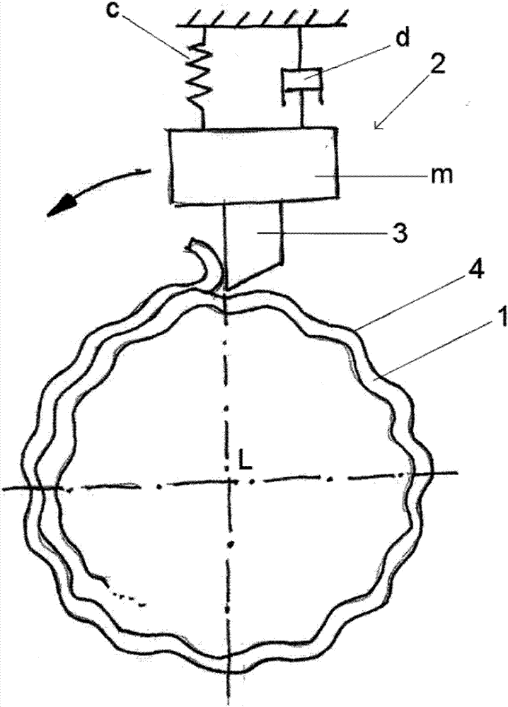
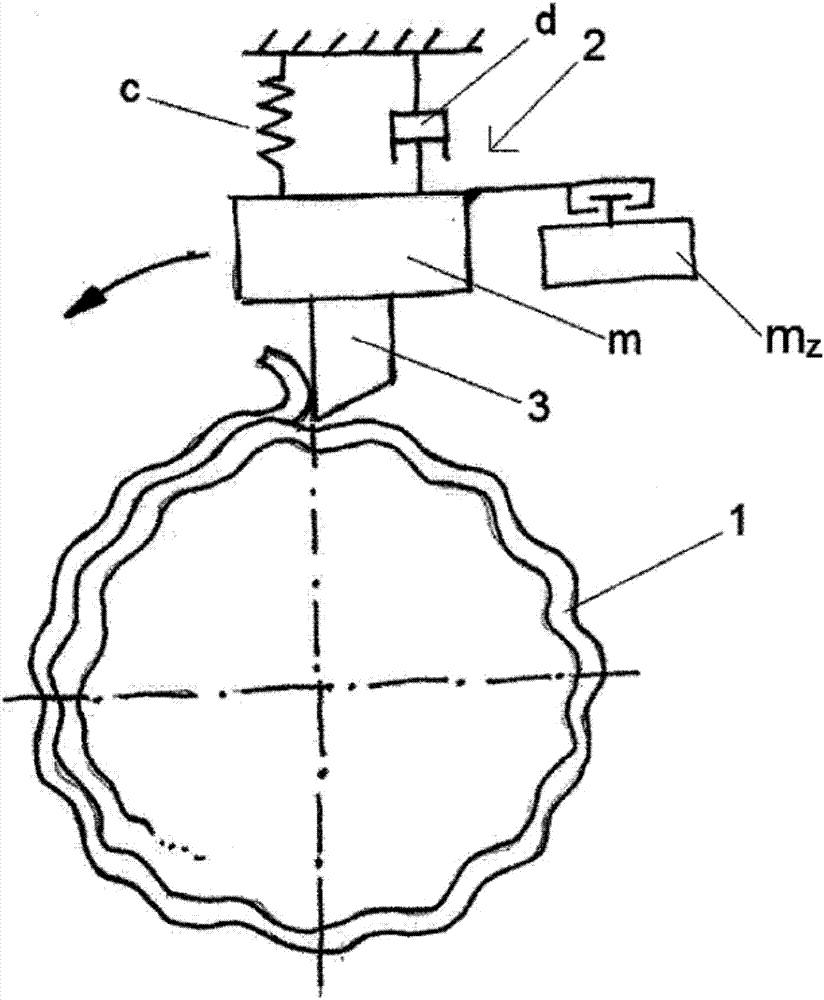
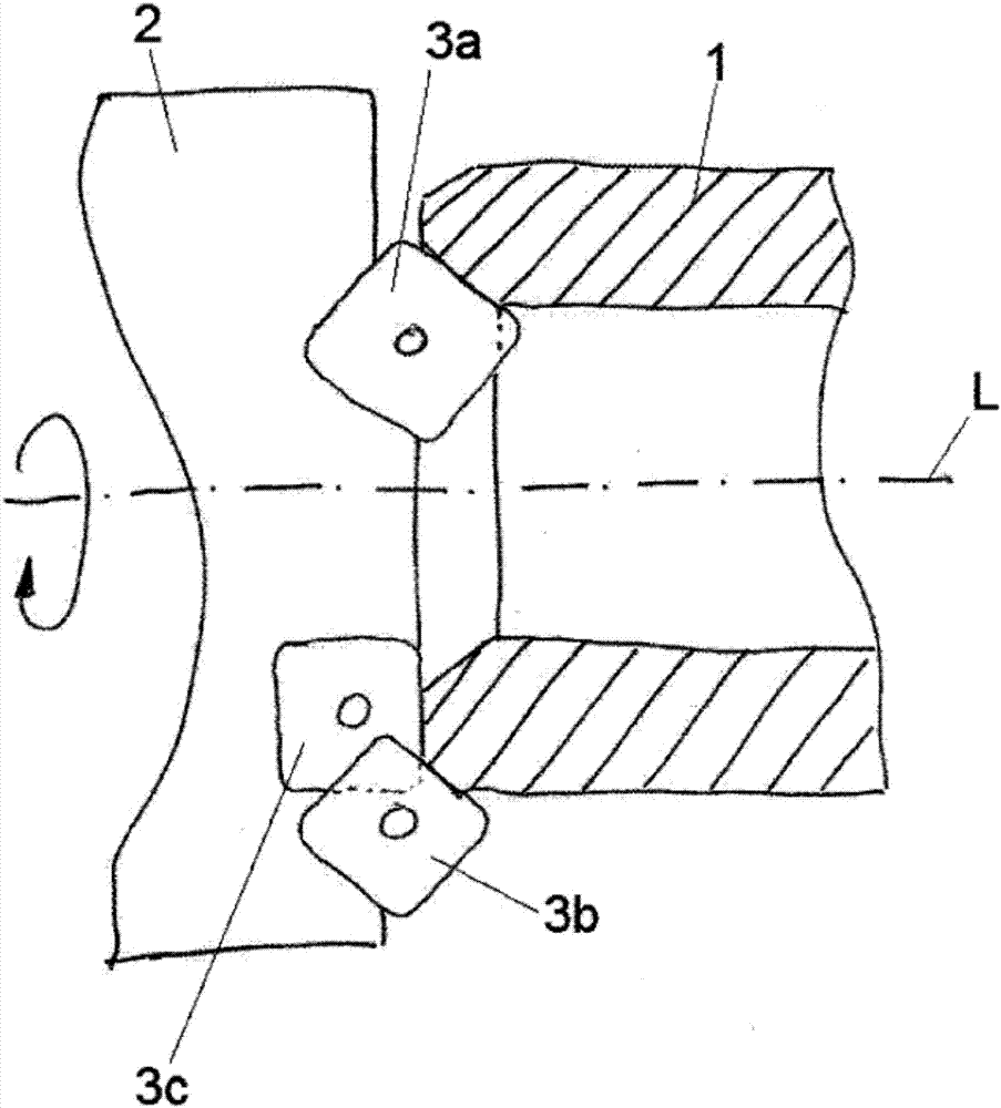
[0041] figure 1 A workpiece of substantially circular cross-section is schematically shown, for example a pipe section 1 which is substantially circular in outer cross-section. However, the workpiece can also be a solid profile or a solid and hollow profile in some parts. The workpiece is preferably made of metal, particularly preferably of steel; however, other materials are also conceivable. The pipe section 1 is processed by a tool head 2 which, in the schematic illustration, has exactly one single blade 3 . Naturally, the tool head 2 can also have two, three or a higher number of blades 3 . The tool head 2 and the pipe section 1 rotate relative to each other. In this case, the tool head 2 can be fixed in space relative to the cutting machine (not shown) and the tube can be rotated about a longitudinal axis oriented in the longitudinal direction L, or the tube section 1 can be fixed in space relative to the cutting machine , and the cutter head 2 is rotatable about the ...


PUM


Abstract

The invention relates to a method for reducing regenerative chatter in that a workpiece (1) rotates in relation to a tool head (2) having at least one chip-removal tool (3, 3a, 3b, 3c) arranged at one end of the tool head (2), the tool head (2) machines walls of the workpiece (1) by means of the at least one chip-removal tool (3, 3a, 3b, 3c), the tool head (2) is vibrationally excited during the machining, a loose additional mass (mz) is moved by the vibration, which additional mass randomly touches the tool head (2) in first positions or randomly has no connection to the tool head (2) in second positions, and thus the total mass of the tool head (2) is randomly changed by the amount of the additional mass (mz) and the vibrational behavior of the tool head (2) is changed because of the mass change and thus counteracts regenerative chatter, and in that a receptacle (51), by means of which the tool head (2) can be exchangeably placed onto a spindle, is arranged at another end of the tool head (2) opposite the one end.

Description

technical field [0001] The invention relates not only to a method for reducing regenerative chatter, in particular for a cutting machine, but also to a cutting machine. Background technique [0002] Cutting machines in the form of rotating combined cutterheads for pipe ends are naturally sufficiently known in the prior art. A tool head is known, for example, from EP 2 106 313 B1. [0003] No. 2,699,696 discloses a drill bit with a spindle, at its outer end a space for attaching weight is provided, wherein the space is closed by a cover. A disadvantage of the drill bit disclosed here is that it can only be used with attached weights. [0004] A vibration-damping tool for machining workpieces is described in DE 10 2009 009 212 B3, in which one or more movable vibration dampers are fixed along the circumference of the tool body. A disadvantage of this tool is that the position of the vibration damper must be precisely determined beforehand in order to damp vibrations as best...

Claims


Application Information

Patent Timeline
IPC IPC(8): B23Q11/00B23B5/16
CPCB23B5/167B23Q11/0035B23B2250/16B23B27/002B23C5/003B23B2215/72B23B2270/30B23Q11/0039
Inventor 乌利齐·拉通德
Owner RATTUNDE
Why Eureka
Try Eureka