Method for Reducing Regenerative Chatter of Cutting Machine

A technology of cutting machine and chatter, which is applied in the direction of turning equipment, turning equipment, tool holder accessories, etc., to achieve the effect of offsetting regenerative chatter and avoiding wave irregularity

Active Publication Date: 2021-01-05
RATTUNDE
View PDF3 Cites 0 Cited by
  • Summary
  • Abstract
  • Description
  • Claims
  • Application Information

AI Technical Summary

Problems solved by technology

[0012] However, the above system for preventing regenerative chatter is particularly delicate and also requires intensive maintenance

Method used


Image

  • Method for Reducing Regenerative Chatter of Cutting Machine
  • Method for Reducing Regenerative Chatter of Cutting Machine
  • Method for Reducing Regenerative Chatter of Cutting Machine

Examples


Embodiment Construction

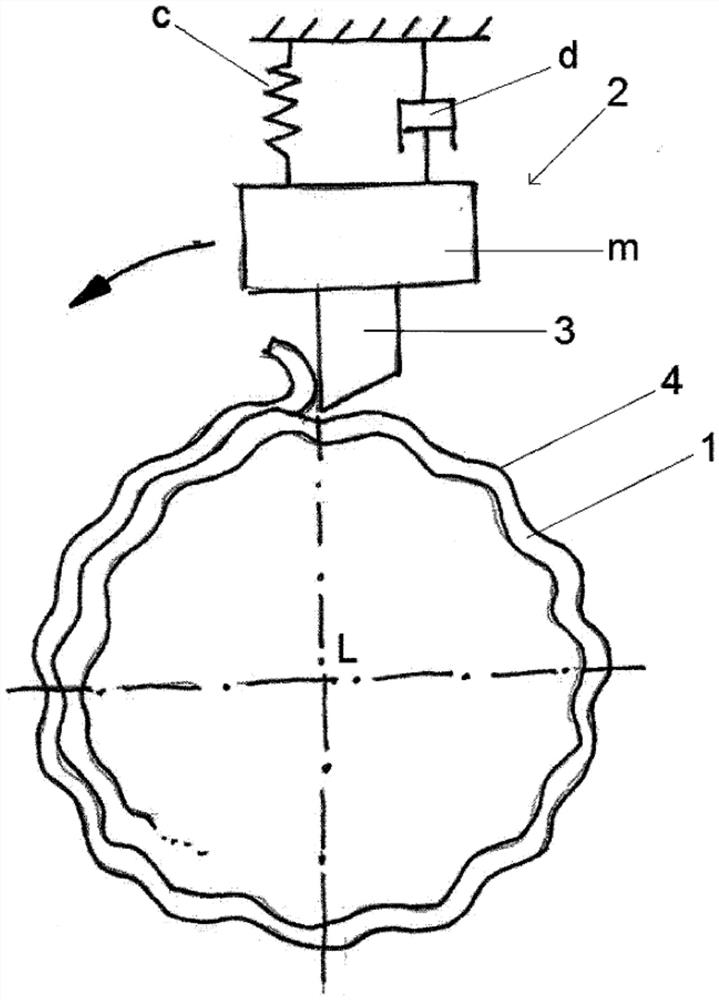
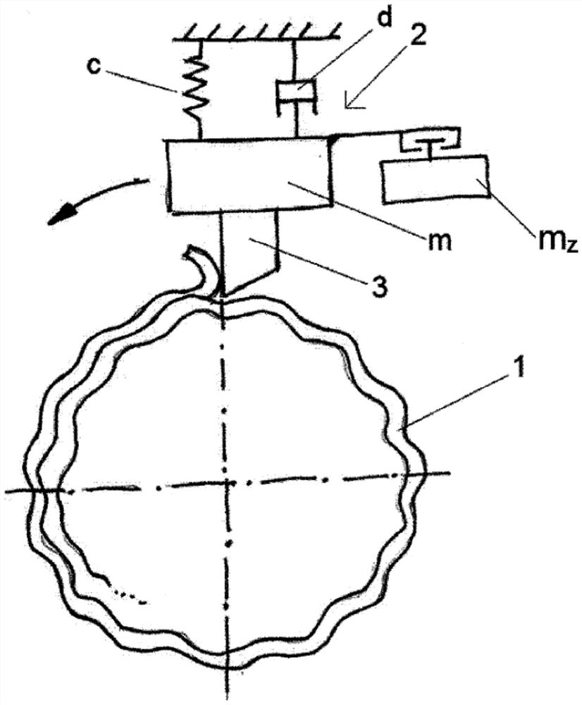
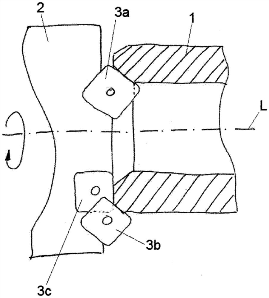
[0041]figure 1 A work piece of substantially circular cross-section is schematically shown, for example, a pipe section 1 that is substantially circular in external cross section. However, the workpiece may also have a solid contour or a solid and hollow contour in some parts. The workpiece is preferably made of metal, particularly preferably steel; however, other materials are also conceivable. The pipe section 1 is machined by a tool head 2, which has exactly one single blade 3 in the diagram. Naturally, the cutter head 2 may also have two, three, or more blades 3. The cutter head 2 and the pipe section 1 rotate relative to each other. In this case, the tool head 2 can be fixed in space relative to the cutting machine (not shown), and the tube can be rotated about a longitudinal axis oriented in the longitudinal direction L, or the tube section 1 can be fixed in space relative to the cutting machine , And the cutter head 2 can rotate around the longitudinal axis of the pipe sectio...


PUM


Abstract

The invention relates to a method for reducing regenerative chatter, wherein a workpiece (1) is rotated relative to a tool head (2) provided at one end with at least one cutting tool (3, 3a, 3b, 3c), the tool head (2) being supported by at least one The cutting tool (3, 3a, 3b, 3c) processes the wall of the workpiece (1), the tool head (2) is excited to vibrate during processing, and the loose additional mass (m z ) moves by vibration, the additional mass randomly touches the tool head (2) at the first position or randomly does not connect with the tool head (2) at the second position, thus through the additional mass (m z ) randomly changes the total mass of the cutter head (2), and through the mass change, changes the vibration characteristics of the cutter head (2), thereby canceling regenerative chatter, and wherein at the opposite end of the cutter head (2) A receiving part (51) is provided at one end, and the cutter head (2) is replaceably installed on the main shaft by means of the receiving part (51).

Description

Technical field[0001]The present invention not only relates to a method for reducing regenerative chatter, especially for cutting machines, but also relates to a cutting machine.Background technique[0002]In the prior art, the cutting machine adopts a rotating combined cutter head for the tube end naturally enough. For example, a tool head is disclosed in EP 2 106 313 B1.[0003]In US 2,699,696, a drill bit with a spindle is disclosed, and a space for attaching weight is provided at its outer end, wherein the space is closed by a cover. The disadvantage of the drill bit disclosed here is that it can only be used with attached weights.[0004]DE 10 2009 009 212 B3 describes a damping tool for machining workpieces, in which one or more movable vibration dampers are fixed along the circumference of the tool body. The disadvantage of this tool is that the position of the vibration buffer must be accurately determined in advance to dampen the vibration as best as possible.[0005]A cutting mach...

Claims


Application Information

Patent Timeline
Patent Type & Authority Patents(China)
IPC IPC(8): B23Q11/00B23B5/16
CPCB23B5/167B23Q11/0035B23B2250/16B23B27/002B23C5/003B23B2215/72B23B2270/30B23Q11/0039
Inventor 乌利齐·拉通德
Owner RATTUNDE
Why Eureka
Try Eureka