Ivc filter retrieval systems with interposed support members

A technology of supporting member and supporting element, applied in the direction of filters in blood vessels, medical devices, stents, etc., can solve the problems of chaotic filter orientation and difficulty in recapturing, etc.

Active Publication Date: 2017-12-01
ALTAI MEDICAL TECH
15 Cites 0 Cited by

AI-Extracted Technical Summary

Problems solved by technology

However, problems are still common as the device is not anchored in the IVC in a stable manner
In addition...

Abstract

Funnel-trap type delivery and/or retrieval devices for Inferior Vena Cava (IVC) filters or other medical implants are described in which the devices comprise two layers of braid with an axially support member. The support member may be interposed between braid layers or set inside the braid layers but interposed between heatset features. Delivery and/or retrieval devices, kits in which they are included, methods of use and methods of manufacture are all contemplated herein.

Application Domain

StentsMedical devices +1

Technology Topic

Biomedical engineeringBraid +1

Image

  • Ivc filter retrieval systems with interposed support members
  • Ivc filter retrieval systems with interposed support members
  • Ivc filter retrieval systems with interposed support members

Examples

  • Experimental program(1)

Example Embodiment

[0027] Various exemplary embodiments are described below. Reference is made to these examples in a non-limiting sense, as it should be noted that these examples are provided to illustrate broader application aspects of the devices, systems, and methods. Without departing from the true spirit and scope of the various embodiments, various modifications may be made to these embodiments and equivalents may be substituted. In addition, many modifications may be made to adapt a particular situation, material, material composition, process, process action(s) or step(s) to the goal, spirit, or scope of the present invention. All such modifications are intended to fall within the scope of protection claimed in this article.
[0028] Before describing the subject matter in detail, it is to be understood that the present disclosure is not limited to the specific example embodiments described, and therefore may of course be varied. It should also be understood that the terms used herein are only for the purpose of describing specific embodiments and are not intended to be limiting, as the scope of the present disclosure will only be limited by the appended claims.
[0029] All the features, elements, components, functions, and steps described with respect to any embodiment provided herein are intended to be combined with and replaced by those features, elements, components, functions and steps from any other embodiment. If only a certain feature, element, component, function or step is described with respect to one embodiment, it should be understood that the feature, element, component, function or step can be used with any other embodiment described herein, unless Also clearly stated. Therefore, this paragraph is used as the pre-foundation and written support for the introduction of the claims. The features, elements, components, functions, and steps from different embodiments can be combined at any time, or use from other embodiments Those features, elements, parts, functions, and steps replace the features, elements, parts, functions, and steps from one embodiment, even if the following description does not explicitly indicate that such a combination or substitution is possible under certain circumstances. It is too cumbersome to explicitly describe each possible combination and substitution, especially considering that a person of ordinary skill in the art will easily realize the permissibility of each such combination and substitution when reading this specification.
[0030] Figure 1A A GUNTHER TULIP (Cook Medical Company) temporary IVC filter 10 is shown with a hook 12 end interface for retraction. As in Figure 1B As shown in the figure, for the IVC filter 20, the hook can be modified or replaced with a block interface 22. The block (itself) may include laser-formed or welded protrusions or bumps 24 on the extension 26 of the hub 28. Instead, as in figure 2 As described above, the filter retraction interface 22 may include a band 24' (for example, a Pt marking band) installed (for example, by swaging, welding, gluing, etc.) on the extension 26. However, the enlarged part is formed, and the funnel capture structure described below is suitable for fixing the components used for the IVC filter retraction.
[0031] figure 2 An overview of the theme system 100 is provided. The funnel capture structure 30 is shown as being made of a heat-set braid material 32. This configuration provides the elongate shaft 34 with a flexible distal extension. The shaft is contained within an elongate cannula 50 (which can be a commercially available catheter or a customized part of the overall system 100) and can include a radiopaque marker band 52 at the distal end.
[0032] The braid may include Nitinol (preferably super-elastic at body temperature), CoCr (cobalt-chromium alloy), stainless steel, or other biocompatible materials. Advantageously, the braid material is included in 72 patterns in 1 up and 1 down (1-over-1), 1 up and 2 down (1-over-2), 2 up and 2 down (2-over-2) or other patterns. And 288 (or between about 144 and 192) filament "ends." With (superelastic) Nitinol, the diameter of the wire is advantageously between about 0.001 and about 0.003 inches. In this case, a soft and relatively "smooth" substrate surface is provided from which the flexible funnel capture framework shown and described is constructed. The value of such a surface lies in its atraumatic appearance and/or its ability to help direct the IVC filter interface in place for capture even when it is oriented obliquely. However, other wire sizes and/or number of ends or other configuration options in the braid are also possible.
[0033] To further facilitate recapture, the funnel capture structure 30 can be selectively guided. Such as figure 2 As indicated by the arrow in the, the material from which the funnel capture structure 30 is made can be heat-set or otherwise configured to provide a bias in an angled direction. As described further, the angle of configuration may be selectable or straightened completely through the relative position of the core member or the closure (not shown) or through the cannula or catheter sheath. As further illustrated, further positioning can be achieved by rotating the device. Alternatively, a curved "L"-shaped or "J"-shaped wire may be housed in the cavity of the shaft 34, which may pass and/or pass to the inside of the funnel capture structure. This member made of super-elastic Nitinol (or other) wire can be used to selectively shape or guide the device end.
[0034] Other device engagement options for selecting the angular orientation of the funnel capture portion of the device are also possible. For this purpose, any of a variety of steerable or steerable catheter-type technologies (relying on a drawing wire or other means) can be incorporated in the shaft 34. Examples include the institutions described in USPN 4,723,936, 4,960,411, 6,251,092, and 8,273,073, the entire contents of each of which are incorporated herein by reference for such description.
[0035] The subject "funnel catch" may have a generally frusto-conical shape as shown or constructed in other ways. Utilizing the outer cone shape (ie, the triangular shape of the cross section as shown), the structure is highly supportive for any necessary or desired tissue discrimination that may need to be performed in order to release the placed filter. Moreover, such a shape provides a flexible "waist" section 48 for the guideable feature(s) mentioned above. However, the device may be bent outward along its sides, or be constructed in other ways without departing from the aspect or variation of the claimed invention.
[0036] Importantly, the distal edge opening 40 of this structure is larger than the more proximal edge opening 42 in order to operate to guide the filter amplifying part(s) or the amplifying part 24/24' into the recess (P), Here, the enlarged part or enlarged part is captured and then locked when the sleeve 50 is advanced.
[0037] Such a recess is formed between the braid wall 44 and the bend 38, and is optionally used as a component adjacent to the edge or shoulder of the block/protrusion 24/24'. To ensure capture, the cannula 50 can be fully advanced on the capture member 30 before retracting into a separate catheter. In other words, the sleeve 50 advancing on the funnel section 30 "closes the catch" and securely catches the implant to be retracted. In addition, the sleeve can be a catheter.
[0038] Obviously, the system 100 can be used in the same way when capturing a filter 10 with a typical hook-shaped end 12. However, the additional protrusion/lateral extension of the hook may require the use of a relatively larger sleeve or catheter 50. In any case, the doctor can see through the use of the system by means of the marking components 24/24' and 52 and/or other components such as can be conveniently provided.
[0039] In various system architectures, the catheter/propeller shaft and/or sleeve can include simple extrusions (eg, PTFE, FEP, PEEK, PI, etc.) or can be constructed using conventional catheter construction techniques and include liners Braid support and sheath (not shown), metal hypotube, etc. In addition, the filter frame may be constructed using conventional laser cutting and electrolytic polishing techniques and/or constructed in other ways. In embodiments intended for tracking through a guide/delivery catheter without a sheath that is bound, a loading sheath may be employed. Advantageously, any such loading sheath is detachable. Other typical percutaneous access devices (such as silk threads, etc.), valves, and other hardware can also be used in combination with embodiments of the present invention.
[0040] The funnel capture structure 30 may be made as a sub-assembly and attached to the catheter/propeller shaft. PCT Publication PCT/US2014/042343 (WO2014201380) and U.S. Patent Application No. 14/569,500 (the entire contents of which are incorporated herein by reference) detail optional steps for manufacturing preforms for construction such as image 3 The funnel capture part of the final device shown in.
[0041] For IVC filter retraction, the illustrated funnel capture portion 30 may have a diameter (D) of about 5 mm to about 20 mm (or more preferably about 10 mm to about 15 mm) (ie, within an average-sized human IVC The size in the working range, such blood vessels are reported to have an average diameter of 20 mm in the range of 13 mm to 30 mm). The length (L) can range from about 10 mm to about 30 mm. The overall taper angle (α) between the braid walls 44 may be between about 30 degrees and about 90 degrees. The angle (β) of the bent portion 36 between the braid wall 44 and the flap 46 may be between about 0 degrees and about 60 degrees, and the flap length (F) may be between about 1 mm and about 10 mm . In short, the funnel capture opening diameter (d) can be between about 5% and about 95% of the diameter (D), depending on the variables mentioned (ie, d, D, L, F, α and β) Choose a combination. At the lower end of the range, the internal "opening" may be substantially closed, so that it must be pushed away during retraction in order to accommodate the proximal engagement component(s) of the implant. At the higher end of the range, the flaps may be placed completely along or in line with the outer layer(s) of the device. As shown, the opening 40 of the funnel catch can be arranged at 90 degrees relative to the device axis. In addition, it can be angled or have more complex shapes, as incorporated in the above-referenced US Patent Application No. 14/569,500 (incorporated herein by reference) Figure 9 to Figure 13 Described.
[0042] The embodiments herein include one or more support members disposed within the funnel capture section or portion of the device. The support member(s) may be interposed between the braid layers or arranged inside the braid layers but interposed between the heat setting components. Figure 4A to Figure 4D The scheme and manufacturing method for forming the aforementioned structure are illustrated.
[0043] Here, the braid 32 is manipulated as (in Figure 4A Middle) Flip the outer layer (OL) on the inner layer (IL) and then flip it back (at Figure 4B Middle) On the inner layer (IL), where the support member 60 is placed and abutted by a positioning part 110 in the form of a shrink tube. in Figure 4B In this, the braid layer is realigned and the diameter of the shrink tube 110 is reduced by applying hot air. in Figure 4C In this case, the funnel capture structure 30 is installed on the pusher member 34 using another sheath shrink sleeve 112. in Figure 4D Here, the final system assembly is shown with an outer sleeve 50 and an optional proximal catheter sheath 114 (including PTFE shrink material or other materials).
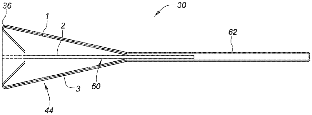
[0044] Figure 5A Provided in Figure 4A to Figure 4D An enlarged view of the funnel catch 30 plus the support structure 60 shown in FIG. Here, the two-layer (IL and OL) structure of the capturing member 30 formed by heat setting the braid 32 is more obvious. In this cross-sectional view, the two "petals" 1 and 3 of the "flower" support structure 60 are also shown. In this example of the four-petal support member embodiment, the petals entering and out of the plane of the figure (otherwise the petals may be numbered 2 and 4) are not shown. However, a part of the cylindrical base or shaft 62 of the support structure 30 is shown in cross section.
[0045] Figure 5B Another support structure embodiment is shown. Here, the individual support members 70 and 72 "fingers" crimped or hooked into a "J" shape are independent of each other and stabilized between the layers of the braid. (in Figure 5B , By convention, the fingers entering and outside the page of the cross-sectional view are not shown). Such component(s) can be further stabilized by (multiple) suture loops, which pass through and/or surround each such component or body, wherein the (multiple) suture loops are fixed A) knot 74 is positioned inside the outer wall 44 of the device.
[0046] The suture may be looped around a single member and interwoven through the braid to form a guide or path. In another aspect, the suture is formed in a loop around the circumference of the braid between the layers of the braid (the dotted circle 76 in the figure represents an option) and is tied to each member. Forming through holes of various locator types in the members 72 and 74 (for example, by laser cutting, hypotube drilling, or other means) can facilitate such a knotting or knotting scheme. Picture 11 An example of such a scheme is shown in (although in a different context).
[0047] in Figure 5C In, such as Figure 5A The support member 60 described in is placed inside the funnel capture structure 30, inside the wall(s) 44 thereof. In this way, the petal member 2 is visible in the drawings and extends to the adjacent bent portion 36 like other petals so as to support the opening edge 40 (as shown by the dotted line).
[0048] In certain aspects, Figure 5D The placement of support members in is similar to Figure 5A The placement of the supporting members in the Figure 5C The placement of support members in the. The difference between these examples is Figure 5D A funnel capture structure 30' including two funnel capture preforms 30a and 30b is shown. Therefore, it can be said Figure 5D The structure uses Figure 5C And add a second internal funnel catch to the construction. Instead, Figure 5D Can be viewed as relative to Figure 5A Double the layers of the scheme.
[0049] anyway, Figure 5D The detailed view in includes five layers (A-D) of material. As shown, layer “C” represents the layer of support member 60. However, other layer combinations are possible, such as ACBDE combination (that is, the support member 60 or members 72 and 74, etc. move one layer outward), ABDCE combination (that is, the support layer is moved one layer inward), or ABDEC Combine (ie, move the support layer inward by two layers). Regardless of how the support is contained, this doubled funnel 30' solution (ie, using sub-assembly 30a plus 30b) can provide benefits when a smaller number of braid ends or smaller diameter threads are desired in a given layer , While maintaining the overall density of the braid.
[0050] Figure 6A with Figure 6B as well as Figure 8A with Figure 8B The manufacturing methods used in some support member embodiments are detailed. Figure 6A A side perspective view of a support member in a cut-like or compressed configuration. in Figure 6A In this, the tube (eg, PET, PTFE, or PEEK) is cut with four slits or grooves to define the four petals 1, 2, 3, 4 of the support member 60, leaving an interconnected support base or sleeve 62. The cutting can be performed with a blade or a laser cutter. The use of laser will also facilitate the addition of an optional pressure release member 64 (shown in dashed lines) at the petal junction.
[0051] When cutting in a metal such as Nitinol, the release member 64 may be necessary. In plastic, the release member 64 is not necessary. In either case, Figure 6A The body shown is advantageously in Figure 6B It is heat-set in the expanded form. This can be combined Figure 7 The tool 80 shown in the figure and a heat setting or heat treatment oven are implemented. The tool may include a shaft or rod 82 to center the support member shaft or sleeve 62 and washers 84a and 84b for flattening petals 1-4.
[0052] Figure 8A A plan view of the support member 60 thus provided is provided. By heat setting the material to be open and flat (or arranged in an approximately conical shape), this structure helps to open up the resilience of the braid 32 in the funnel capture structure 30 when configured. Figure 8B It is illustrated how the first support member 60a can be nested with the second support member 60b to form a combined support member 60'.
[0053] In this case, the nesting doubles the number of supporting petals. This solution (ie, nesting at least two support member subassemblies) provides the maximum number of petals, where each petal has the largest possible petal width (compared to cutting multiple petals from a single tube). When constructed from thin materials (for example, on the order of 0.002 to about 0.005 inches thick) and/or avoid pushing or piercing the braid that the member is intended to support, the maximum width can be used to provide lateral stability to the element Is particularly useful.
[0054] Picture 9 Another aspect of the structure of the support member is illustrated. Here, the support 120 is constructed using a tube heat-shrinked or formed to the core rod 130 (for example, PET or PEEK heat-shrinking). The cylindrical portion 132 of the core rod provides the circular interface portion 122 of the support for mounting to the device shaft 34. The flat portion 134 on the core rod forms the flat portion or petal 124 in the support. When initially formed by heat shrinking on the core rod, the petals are connected. However, use scissors, razor blades or other tools to cut the petals along the square edge (dashed line) formed by the edge 136 of the core rod.
[0055] One such support can be used in a configuration as described above. In addition, a pair (or more) of support members can be nested coaxially. When stacked or nested, as before, the petals are advantageously offset from each other. A symmetrical offset of 45 degrees is advantageous for each supporting member including four petals, so a combined structure with eight symmetrically arranged supporting petals is provided. In the case of nesting the support members formed with three petals with each other so as to form a final configuration with six petals, the offset between each petal is advantageously 60 degrees.
[0056] Moreover, the petals can be plastically deformed and are set to expand outward. In the heat shrinkable embodiment, this should be done mechanically (ie, without substantial heating) in order to avoid unintentional forming (misforming) due to unintentional restoration of the heat shrinkable tube. However, when two supporting bodies are used in a coaxial structure, a soldering iron tip can be used to heat-fuse them together by cross penetration (or join them in other ways, for example, by an adhesive between the bodies ) In order to maintain the desired spacing of petals or for any other reason. The same scheme (ie, hot melt, etc.) can also be combined Figure 8B The example uses.
[0057] Picture 10 Another aspect of the structure of the support member is illustrated. Here, the support 140 is configured on the end of the shaft 34 (as shown) or used as a separate sub-assembly similar to the other examples above. Regardless, the support includes a plurality of independent extension members 142. These independent extension members can be formed by die cutting or laser cutting PET, PEEK or another sheet. And then it is positioned to the support body via the guide or viewing hole 144 as shown. The viewing hole can be aligned along axis 146 with a wire (wire axis shown) that is removed after fixing the complementary component (eg, gluing, laser welding, or fusion by typical catheter construction techniques or other techniques) .
[0058] Picture 10 The structure in can be used in Picture 11 The support member shown in the nesting scheme. Alternatively, the tubular shaft 34 can be processed so that its distal end is cut into a support member section 90 with finger or petal extensions 91, 92, 93, etc. These extensions can be combined like Figure 7 It is heat-set as described or is heat-set into a tapered shape using matching tools or forms. For forming or heat setting purposes, the shaft advantageously comprises PET or PEEK (because such a choice provides a good compromise in strength, machinability, and formability) or Nitinol. The cutting may be performed with a laser and includes a stress relief member 96 at the junction of the shaft main body 34 and the extension. An optional zig-zag end piece 98 may also be included in this configuration. These zigzag square-waves or other such engagement components can help maintain a stable position of the support member fingers when the braid of the edge opening 40 is compressed and is in contact with the component. Obviously, the same such components can be included as shown in Picture 10 and / or Figure 12A with Figure 12B Or be included in other embodiments as provided herein.
[0059] in Picture 11 In, the funnel catch embodiment 30 also includes an optional second support member 60 interposed between its braid layers (IL and OL). Obviously, the fingers 1 and 2 of the support member 60 are advantageously staggered or intersected with the mating extensions 81 and 82 (such as Figure 8B In order to maximize the number of non-overlapping elements and to provide the opening edge 40 with a uniform spacing of radial support points.
[0060] In such a system 100, the extension section 30 may be positioned as shown and bonded to the shaft 34 with one or more PEBAX (or other thermoplastic material) layers 102. Laser welding schemes are also possible, especially for embodiments where all components are made of Nitinol, but other materials can also be used to achieve the same effect.
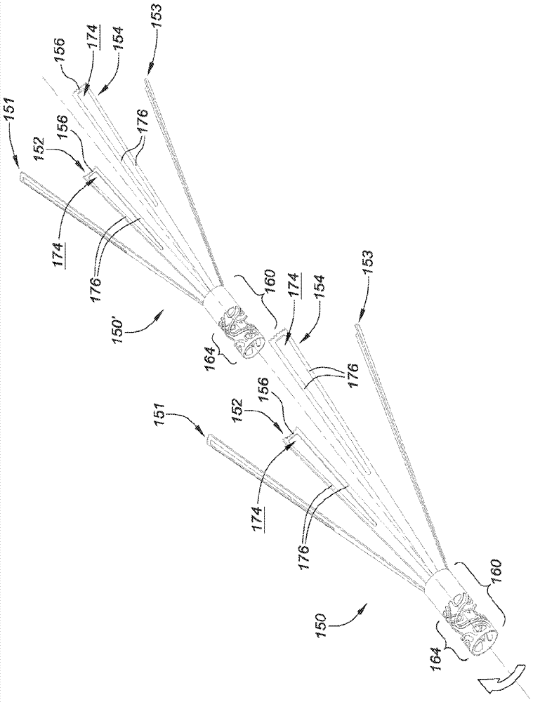
[0061] Figure 12A Illustrated is a laser cut pattern that can be used to cut the extension section of the shaft as discussed above. Alternatively, the pattern may define the geometry of the individual support 150 as shown.
[0062] In either case, the shape includes a plurality of extensions 151, 152, 153, and 154 in the form of substantially triangular petals, fingers, or leaves. By being configured in this way, the size of the available distal interface area 156 of each member for supporting the funnel capture braid 32 is maximized while minimizing the waist or curved section 158 of each petal. This minimized waist provides space for the (optional) radial stress relief component 160 of the base or shank section 160.
[0063] The support member 150 may be so cut from Nitinol tube or other materials. The cutting pattern may include an open stress relief area 164 that includes a plurality of curved or otherwise configured beams 166 within the shank section 160. Such sections will serve as one or more windows for the flow of bonding materials (eg, thermoplastic PEBAX or other materials as mentioned above) without significantly increasing the stiffness on the entire base 160 of the structure. Alternatively, a square or rectangular shaped window may be provided for bonding. In either case (ie, with complex curved windows or straight forms), the windows in each base are advantageously set or "clocked" so that when the windows are aligned for the flow of the bonding material The obsolete extensions 151 and the like are spaced apart as needed. The proximal edge or band 168 of each support member 150 and 150' will prevent pulling out from the flow-through joint solution.
[0064] The wide proximal or distal edge or band 170 (ie, as shown) can actually be used as an overall radiopaque marker for the constructed system. As another option, the inner length or "frame" portion of one or more aligned windows can be laser welded together to stabilize the position of the entire support members 150 and 150' for further assembly processing. Yet another option is to laser or resistance weld the proximal or distal edges or bands 168 and 170 for such purpose(s).
[0065] Furthermore, each edge (or an overall edge without an intermediate stress relief section or region 164) can be split as shown, even if it is cut from a cylindrical tube. Split line 172 can be used to nest one such tube with another tube. If the slit or separation of the split line is wide enough, the base 160 may be compressed and fit in another tube that initially has the same size. Alternatively, split pairs can be employed, where one shrinks and the other expands.
[0066] Figure 12B The assembly of a pair of support members 150 and 150' is illustrated. In this example, none of the bases are split. On the contrary, the size of the tube in which the pattern is cut is designed to nest with each other. The base 160 of each body may include a concavo-convex pattern 164 configured to match when it is coaxially arranged with each other and offset (as indicated by the curved arrow), so that the so-called finger or The petals will not overlap. Alternatively (as shown), the concavo-convex patterns can be configured so that they are not aligned with offset petals. Such a scheme can provide more uniform flexibility.
[0067] For use, the petal extensions 151 and 152 etc. are generally heat set outwards (as shown) and the end interface section 156 may retain the original curvature of the tube cut from it. In this case, any included zigzag end pattern and internal asperities 174 can provide flexibility when opening or configuring the funnel capture device. In addition, for one or both of the support members 150 and 150', the interface section may be flat (or at least partially flat) heat set. In this case, the aforementioned flexibility will help to completely compress the device for tracking and/or retrieval. In the event that such a pattern is not provided, if so desired, the width or thickness of the associated component can be changed.
[0068] With the concave-convex section 174, the distal interface 156 (whether serrated, flat, or other configuration) is partially shown as being supported by the strut 176. Alternatively, the uneven space 174 may be omitted. Such an embodiment (not shown) may employ a single central pillar as part of an overall "T"-shaped body.
[0069] In any case, Figure 13 This is an end view of the funnel section 30 of the device 100, where the support member 150/150' is disposed within the braid material 32. Through the braid, it can be observed that the alternating petals X and Y are wider and narrower, respectively. This is the result of cutting the largest width interface section 156 from the larger and smaller tubes, respectively, for nesting.
[0070] With the split tube solution, the same size interface section 156 can be provided. However, when compressed, the narrow "Y-shaped" member can be compressed better (ie, compressed to its original tube size), thereby providing a reduced crossover configuration of the device. In other words, if a mixture of X and Y-shaped or design-size components is provided, excessive size stacking can be avoided. If used, such considerations are useful in minimizing the size of the locking sleeve 50.
[0071] Variations
[0072] The subject methods (including methods of use and/or manufacturing) can be performed in any sequence of events that is logically possible, as well as in any described sequence of events. The medical method may include any medical staff activity associated with device provision, implant positioning, repositioning, retraction, and/or release.
[0073] In addition, in the case of providing a range of values, it is to be understood that every intermediate value between the upper limit and the lower limit of the range and any other stated value or intermediate value in the stated range are covered by the present invention Inside. Moreover, it is conceivable that any optional feature of the described variants of the invention may be set forth or claimed separately, or in combination with any one or more of the features described herein.
[0074] Although the present invention has been described with reference to multiple examples (optionally containing multiple features), the present invention is not limited to the examples described or indicated, as conceived for each variant of the present invention. Without departing from the true spirit and scope of the present invention, many modifications can be made to the described invention and equivalents can be used (whether described herein or not included for a certain degree of brevity) Instead.
[0075] References to singular items include the possibility that there are multiple identical items. More specifically, when used herein and in the appended claims, the singular forms "a", "an", "said" and "the" include plural reference objects, unless specifically stated otherwise. In other words, the use of articles allows for the subject matter of "at least one" in the above description and in the following claims. It is further noted that the claims can be drafted to exclude any optional elements. In this way, the statement is intended to be used as the prior basis for the use of exclusive terms such as "uniquely" and "only" together with the description of claim elements, or as the prior basis for the use of "negative" restrictions.
[0076] Without using such exclusive terms, the term "comprising" in the claims shall allow any additional elements to be included, regardless of whether a given number of elements are listed in the claims, or the addition of features can be seen To change the nature of the elements stated in the claims. Except for those clearly defined in this article, all technical and scientific terms used in this article should be as broad as possible with conventional meanings while maintaining the validity of the claimed protection. Therefore, the scope of the different embodiments or aspects of the present invention described herein should not be limited to the provided examples and/or subject description, but only by the language of the resulting claims.

PUM

no PUM

Description & Claims & Application Information

We can also present the details of the Description, Claims and Application information to help users get a comprehensive understanding of the technical details of the patent, such as background art, summary of invention, brief description of drawings, description of embodiments, and other original content. On the other hand, users can also determine the specific scope of protection of the technology through the list of claims; as well as understand the changes in the life cycle of the technology with the presentation of the patent timeline. Login to view more.
Why Eureka
Try Eureka