Dual diaphragm microphone

A microphone and diaphragm technology, applied in the field of microphones, can solve problems such as affecting the output signal of the microphone

Inactive Publication Date: 2017-12-01
QUALCOMM INC
View PDF5 Cites 4 Cited by
  • Summary
  • Abstract
  • Description
  • Claims
  • Application Information

AI Technical Summary

Problems solved by technology

Microphones in these devices are often subjected to vibration or accele

Method used


Image

  • Dual diaphragm microphone
  • Dual diaphragm microphone
  • Dual diaphragm microphone

Examples


Embodiment Construction

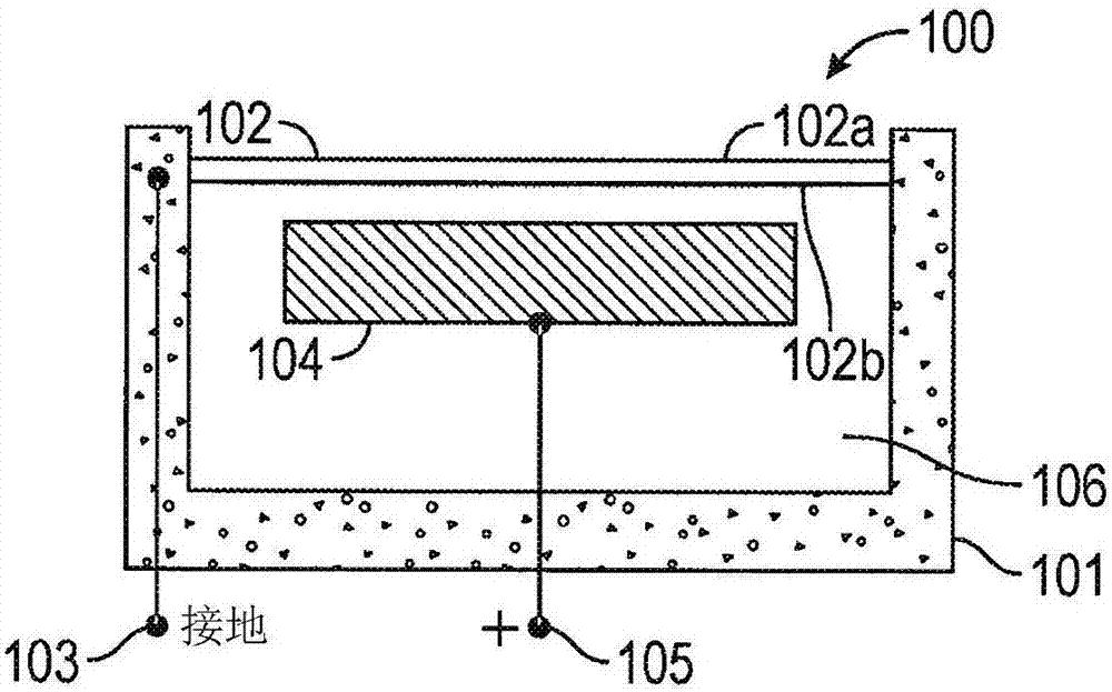
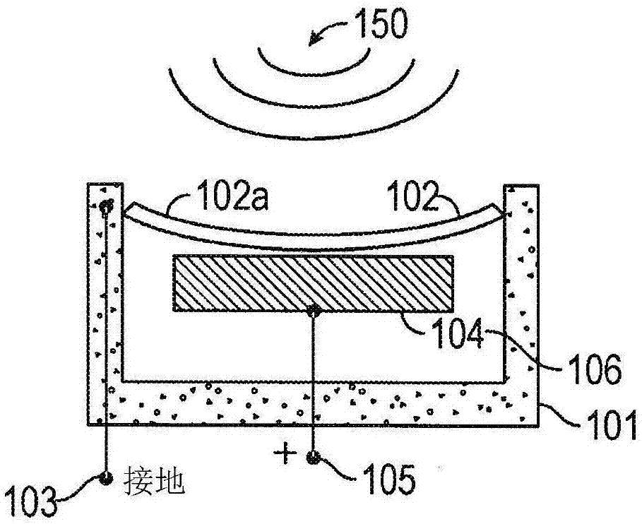
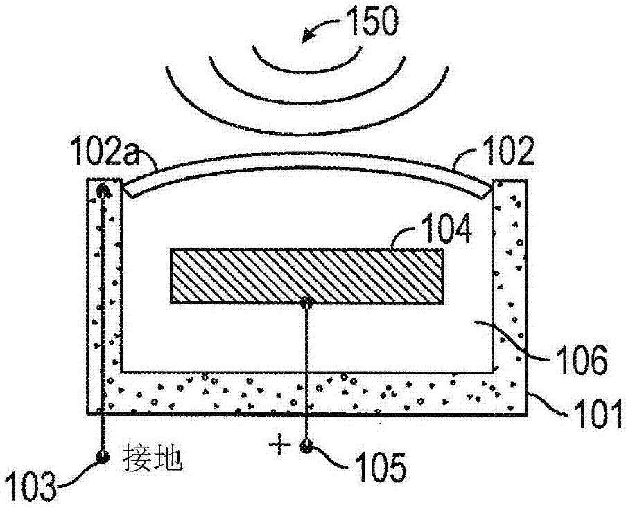
[0026] This disclosure discusses microphone devices, systems and methods configured to reduce or eliminate components of the output signal that may be caused by physical acceleration or vibration of the microphone itself. In general, some implementations of microphones use a membrane to detect changes in air pressure caused by sound pressure waves and convert the displacement of the membrane into an electrical signal indicative of the sound wave. However, displacement of the microphone membrane can also be induced by movement or vibration of the microphone, and such displacement of the microphone membrane will also generate or change the output signal of the microphone. Signal components induced by such accelerations may be indistinguishable from signals produced by incident acoustic waves. In some embodiments, a dual-diaphragm microphone can be configured such that it produces a combined output signal that is substantially unaffected by acceleration or other movement of the m...


PUM


Abstract

A dual diaphragm microphone can be used to reduce or eliminate a component of the output signal due to acceleration of the microphone. The dual diaphragm microphone can include a first sound-detecting component including a first diaphragm spaced apart from a first electrode and configured to generate a first signal and a second sound-detecting component including a second diaphragm spaced apart from a second electrode and configured to generate a second signal. The first sound-detecting component and the second sound-detecting component are oriented in opposite directions and include electronic circuitry configured to sum the first and second output signals to generate a combined output signal substantially unaffected by acceleration of the microphone.

Description

technical field [0001] The present invention relates to microphones. In particular, the present invention relates to microphone devices, systems and methods configured to generate an output signal that is substantially free of components caused by mechanical vibration or physical acceleration of the microphone. Background technique [0002] Some microphones use a deformable diaphragm to convert sound into an electrical signal. Sound in the form of pressure waves deforms the diaphragm to produce an output signal that is proportional to the change in pressure acting on the diaphragm. Mechanical vibration or physical acceleration of the microphone itself can also deform the diaphragm. Deformations induced by vibration or acceleration can also create or affect the output signal of the microphone. Thus, the microphone may generate an output signal comprising a first component indicative of sound waves incident on the microphone and a second component caused by vibration or acc...

Claims


Application Information

Patent Timeline
IPC IPC(8): H04R19/04
CPCH04R3/005H04R19/04H04R2410/05H04R1/08H04R1/222H04R7/02H04R19/005H04R23/006H04R2201/003
Inventor 朴勋真
Owner QUALCOMM INC
Why Eureka
Try Eureka