Underground communication optical cable trench

An underground communication and optical cable technology, applied in optical fiber/cable installation, optics, light guide, etc., can solve problems such as difficulty in meeting the laying requirements of large-capacity communication cables and narrow inner diameter of pipes

Inactive Publication Date: 2017-12-08
吉林吉大通信设计院股份有限公司
View PDF10 Cites 0 Cited by
  • Summary
  • Abstract
  • Description
  • Claims
  • Application Information

AI Technical Summary

Problems solved by technology

[0003] At present, most of the traditional optical cable laying methods use single-hole or porous plastic pipes, and each section of the pipe is connected through manholes to form an underground communication pipe. With the rapid development of , transformation and informatization, the number of new construction, reconstruction and expansion projects of communication optical cable lines is increasing, and the demand for optical cables is increasing. The capacity of ordinary communication pipelines can no longer meet the needs of a large number of cables and line transformation.

Method used


Image

  • Underground communication optical cable trench
  • Underground communication optical cable trench
  • Underground communication optical cable trench

Examples


Embodiment Construction

[0029] The core of the present invention is to provide an underground communication optical cable trench, which can accommodate more communication cables, is convenient for operators to enter and exit, and can meet the requirements of later reconstruction and expansion.

[0030] In order to enable those skilled in the art to better understand the technical solution of the present invention, the underground communication optical cable trench of the present invention will be described in detail below in conjunction with the accompanying drawings and specific implementation methods.

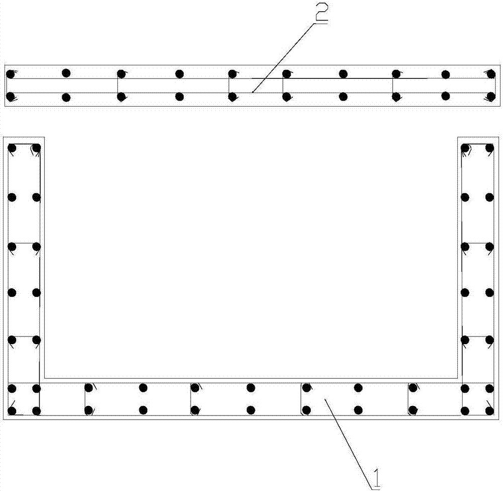
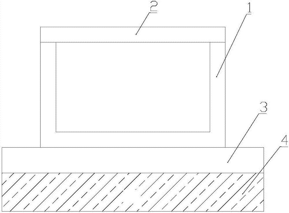
[0031] The invention discloses an underground communication optical cable trench, which is buried underground and is an underground channel for accommodating and distributing communication optical cables, including a reinforced concrete prefabricated pipe groove 1 and a cover plate 2, such as figure 1 As shown, it is a relative position relationship diagram of reinforced concrete prefabricated pipe g...


PUM


Abstract

The invention discloses an underground communication optical cable trench. A precast reinforced concrete pipe groove and a cover plate are matched to form a laying channel extending laterally. Multiple laying channels are communicated with one another and in butt joint. Communication cables are fixedly located on the inner walls of the precast reinforced concrete pipe grooves. An operation channel for people to pass is reserved in the middle of the precast reinforced concrete pipe grooves, which makes it easy for an operator to pass for renovation and extension. The laying channels with greater inner diameter can accommodate more communication cables, have greater accommodating capacity, and provide ample space for later renovation and extension. The precast reinforced concrete pipe grooves are provided with through water outlets at the bottom. Branch holes are arranged in the side walls of the precast reinforced concrete pipe grooves according to actual needs, the communication cables can be connected to the outside through the branch holes, and bifurcation and connection of the communication cables are facilitated. Branch hole positions can be reserved according to the actual needs, the position layout of the branch holes is flexible, and the degree of freedom of line distribution is improved.

Description

technical field [0001] The invention relates to the technical field of optical cable laying, and further relates to an underground communication optical cable trench. Background technique [0002] According to the requirements of urban construction, outdoor communication facilities must be constructed in a concealed way. Generally, underground pipelines or underground direct burial methods are used. In order to ensure the safety of communication facilities, optical cables are mostly laid in underground communication pipelines, which not only meets the needs of communication services, It does not affect the appearance of the city. [0003] At present, most of the traditional optical cable laying methods use single-hole or porous plastic pipes, and each section of the pipe is connected through manholes to form an underground communication pipe. With the rapid development of , transformation and informatization, the number of new construction, reconstruction and expansion proj...

Claims


Application Information

Patent Timeline
Patent Type & Authority Applications(China)
IPC IPC(8): G02B6/50
CPCG02B6/504
Inventor 张青山于沆吕邦国乔元志金谊晶郑林涛刘显禹曹景涛张雪峰裴峰苏朝霞赵欣李忠
Owner 吉林吉大通信设计院股份有限公司
Why Eureka
Try Eureka