
Garment steamer nozzle capable of controlling air outlet range

A technology of a garment steamer and a spray head, which is applied in the field of garment steamers, can solve the problems of small steam volume, time-consuming and laborious, and unsatisfactory effects of the steamer, and achieve the effect of stable movement direction.

Active Publication Date: 2017-12-15
SUZHOU HAIGE ELECTRICAL TECH CO LTD
View PDF5 Cites 1 Cited by
  • Summary
  • Abstract
  • Description
  • Claims
  • Application Information

AI Technical Summary

Problems solved by technology

[0003] However, the steam volume of garment steamers is often relatively small. Compared with irons, it takes time and effort to deal with heavily wrinkled clothes, and the effect is not satisfactory. Therefore, without changing the steam generation efficiency of garment steamers, how to effectively Using steam to treat heavily wrinkled clothes is a problem to be solved

Method used


Image

  • Garment steamer nozzle capable of controlling air outlet range
  • Garment steamer nozzle capable of controlling air outlet range
  • Garment steamer nozzle capable of controlling air outlet range

Examples


Embodiment 1

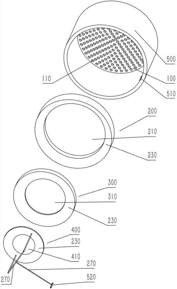
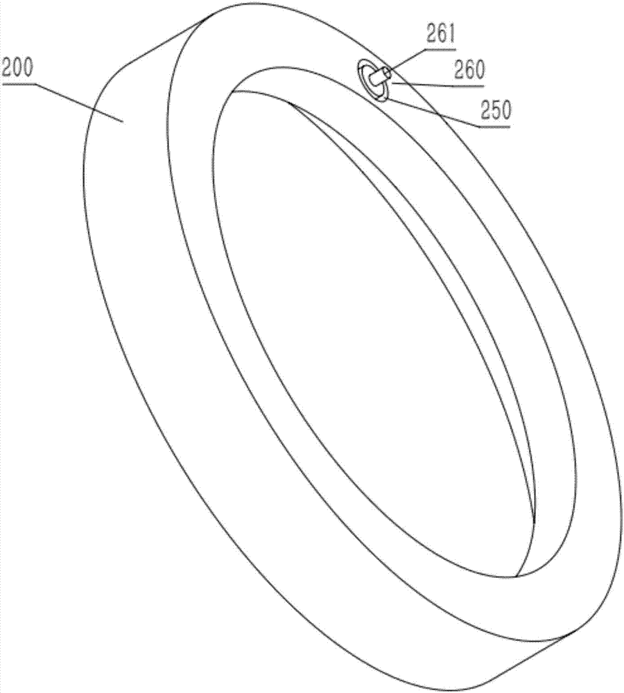
[0034] A spray head of a garment steamer capable of controlling the air outlet range, comprising: an air outlet plate 100, on which air outlet holes 110 are uniformly arranged; Plate 300 and the third moving plate 400, the diameter of the first moving plate 200 is equal to the gas outlet plate 100, the center of the first moving plate 200 is provided with a first through hole 210, the second moving plate 300 The diameter is equal to the first through hole 210, the second through hole 310 is opened in the center of the second moving plate 300, the diameter of the third moving plate 400 is equal to the second through hole 310, and the second through hole 310 is opened in the center of the second moving plate 300. The center of the three movable plates 400 is provided with a third through hole 410; the housing 500, one end of which accommodates the air outlet plate 100, and the control panel is arranged on the side of the air outlet plate 100 inside the housing 500;

[0035] Wher...

Embodiment 2

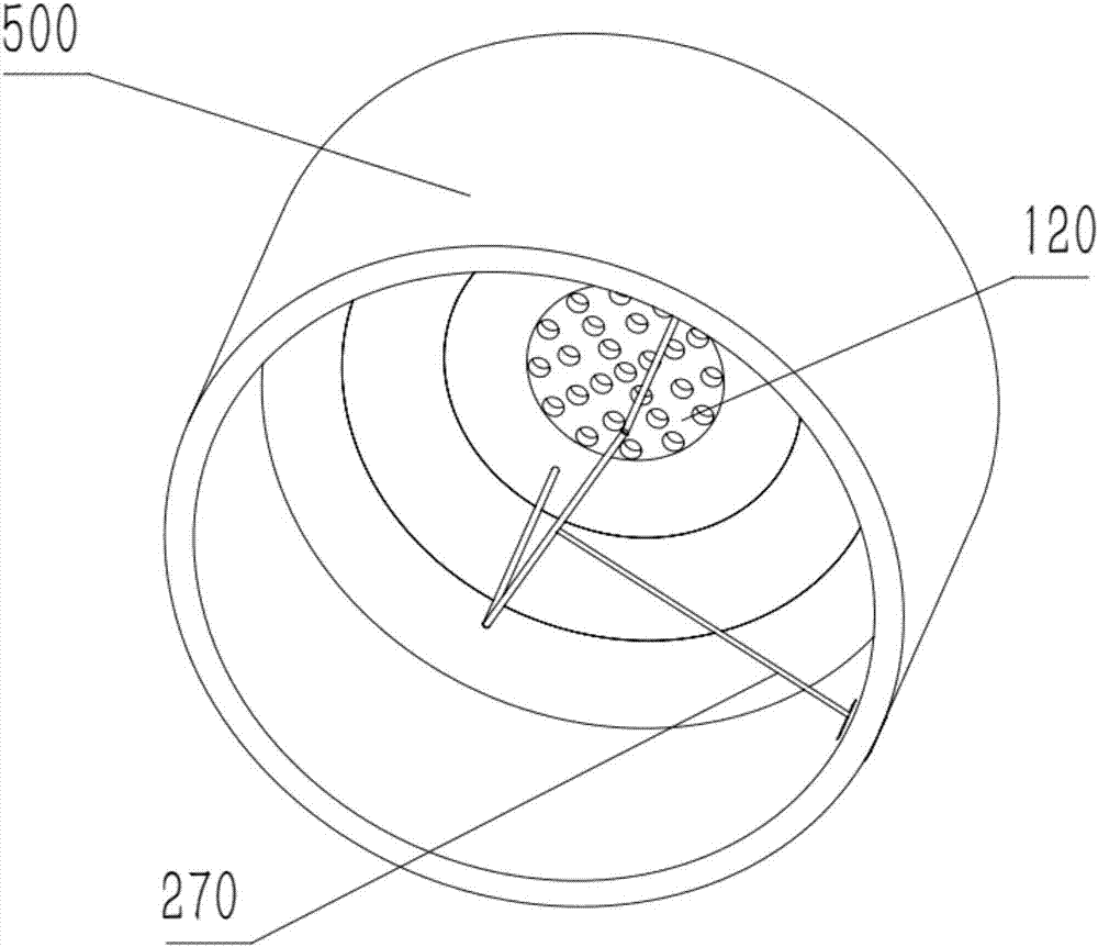
[0039] In this embodiment, the control of the moving plate is directly through manual switching, and the second ends 230 of the first moving plate, the second moving plate and the third moving plate are provided with a connecting rod 270 . The shell 500 is provided with a long hole 510 , a sliding switch 520 is slidably disposed on the long hole 510 , and the sliding switch 520 is fixedly connected with the connecting rod 270 . The sliding switch 520 has an interference fit with the elongated hole 510 , and the covered area of ​​the sliding switch 520 is larger than the elongated through hole, so as to prevent steam from escaping through the sliding switch 520 . The position of the moving plate can be changed by manually manually toggling the slide switch 520 .

[0040] The center of the air outlet plate 100 is a detachable sub-plate 120 , and the diameter of the sub-plate 120 is equal to that of the third through hole 410 . The diameter of the third through hole 410 is 0.2-0...


PUM


Abstract

The invention relates to a garment steamer nozzle capable of controlling the air outlet range. The garment steamer nozzle comprises an air outlet plate, a control panel and a shell, wherein air outlets are evenly distributed in the air outlet plate, the control panel is provided with a first motion plate, a second motion plate and a third motion plate which are coaxial with the air outlet plate, the diameter of the first motion plate is equal to that of the air outlet plate, a first through hole is formed in the center of the first motion plate, the diameter of the second motion plate is equal to that of the first through hole, a second through hole is formed in the center of the second motion plate, the diameter of the third motion plate is equal to that of the third through hole, and a third through hole is formed in the center of the third motion plate; the first end of the shell contains the air outlet plate, and the control panel is arranged on the side, inside the shell, of the air outlet plate. The garment steamer can collect steam and perform local treatment on a garment with serious wrinkles.

Description

technical field [0001] The invention relates to the field of garment steamers, in particular to a nozzle of a garment steamer capable of controlling the air outlet range. Background technique [0002] After the garment steamer is powered on with water, the inner core uses a heater to vaporize normal temperature water into high temperature and high pressure water vapor, and releases the hot water vapor through the steam conduit and nozzle. Spray at the creases of the clothes during use, and use trouser line clips, hair brushes, dust brushes, ironing liners and other hanging ironing machine accessories to smooth clothes and fabrics through the actions of "pull", "press" and "spray". Make the clothes smooth, soft and remove mites, bacteria and dust. [0003] However, the steam volume of garment steamers is often relatively small. Compared with irons, it takes time and effort to deal with heavily wrinkled clothes, and the effect is not satisfactory. Therefore, without changing ...

Claims


Application Information

Patent Timeline
Patent Type & Authority Applications(China)
IPC IPC(8): D06F73/00
CPCD06F73/00
Inventor 陆苏忠
Owner SUZHOU HAIGE ELECTRICAL TECH CO LTD
Learn More