
Rod compression type power connection fixture

A technology of tilting and splicing, applied in the direction of conductive connection, electrical component connection, connection, etc., can solve the problems of limited connection stability, applicability and practicality of power fittings, etc., to ensure the stability, reliability and practicability of the connection. Good and adaptable effect

Active Publication Date: 2019-04-23
YONGXIN ELECTRICAL TECH GRP CO LTD
View PDF11 Cites 0 Cited by
  • Summary
  • Abstract
  • Description
  • Claims
  • Application Information

AI Technical Summary

Problems solved by technology

[0002] In the construction of power lines, the cables need to be branched or connected during use. At this time, it is necessary to use power fittings to connect the two wires together to ensure the conduction of the cables. The traditional technology of power fittings is mainly composed of a support and a cover plate. Composition, tooth tips are evenly arranged on the pressure surface of the support and the cover plate, and the support and the cover plate are fixed by bolts, so that the tooth tips penetrate the insulation layer of the cable and make the cable conduct. However, the traditional technology The connection stability of power fittings is relatively limited, so the applicability and practicability are limited

Method used


Image

  • Rod compression type power connection fixture

Examples


Embodiment 1

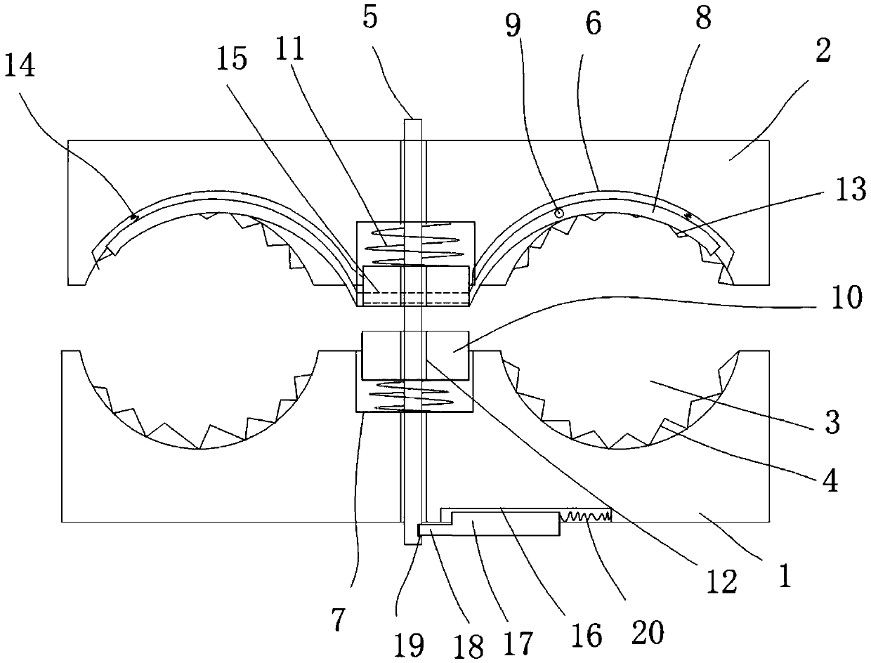
[0014] figure 1 A specific embodiment of the invention is shown in which figure 1 It is a structural schematic diagram of the present invention.

[0015] See figure 1 , a clamping rod pressing type electric power extension fixture, including a pressure seat 1 and a gland 2, an arc-shaped wire groove 3 is arranged on the crimping surface of the pressure seat and the gland, and an arc-shaped wire groove 3 is arranged on the pressure seat 1 and the gland. The arc-shaped wire groove of the gland 2 is evenly provided with tooth tips 4, the pressure seat and the gland are provided with fastening screws 5, and grooves 6 are arranged on the pressure seat and the gland, and the concave Groove 6 is vertically arranged with described arc-shaped wire groove 3, and the middle part of described pressure base 1 and gland 2 is provided with pressure plate groove 7, and described pressure plate groove 7 is parallel with described arc-shaped wire groove 3, in the The groove 6 is provided wit...


PUM


Abstract

The invention discloses a warped rod compression type power-connection clamp comprising a compressing base and a gland. Arc guiding slots are formed in compression surfaces of the compressing base and the gland; and tooth tips are arranged uniformly on the arc guiding slots of the compressing base and the gland. Fastening screw rods are arranged on the compressing base and the gland. Grooves are formed in the compressing base and the gland and are perpendicular to the arc guiding slots. Pressing plate slots are formed in the middle of the compressing base and the gland. Arc warped rods are arranged in the grooves; and the middle parts of the arc warped rods are connected in to the grooves by rotating shafts. Pressing plate bodies are arranged in the pressing plate slots; and springs are arranged between the pressing plate bodies and the pressing plate slots. On end of each arc warped rod is fixed at the side of one pressing plate body. Screw rod holes are formed in the pressing plate bodies and the fastening screw rods penetrate the screw rod holes. The warped rod compression type power-connection clamp has a reasonable structure; and stable and reliable connection of the cable is guaranteed. A loosening or shedding phenomenon is avoided; the usage stability, adaptability, and practicability are high.

Description

technical field [0001] The invention belongs to the technical field of electric power equipment, and in particular relates to a rod pressing type electric power connection fixture. Background technique [0002] In the construction of power lines, the cables need to be branched or connected during use. At this time, it is necessary to use power fittings to connect the two wires together to ensure the conduction of the cables. The traditional technology of power fittings is mainly composed of a support and a cover plate. Composition, tooth tips are evenly arranged on the pressure surface of the support and the cover plate, and the support and the cover plate are fixed by bolts, so that the tooth tips penetrate the insulation layer of the cable and make the cable conduct. However, the traditional technology The connection stability of power fittings is relatively limited, so the applicability and practicability are limited. Contents of the invention [0003] The object of th...

Claims


Application Information

Patent Timeline
Patent Type & Authority Patents(China)
IPC IPC(8): H01R4/24H01R11/12
CPCH01R4/2404H01R11/12
Inventor 卞毓平
Owner YONGXIN ELECTRICAL TECH GRP CO LTD
Learn More