A clamping rod pressing type electric power connection fixture and its working method

A technology of tilting and splicing, which is applied to electrical components, equipment for connecting/terminating cables, etc., can solve problems such as applicability and practical limitations, and achieve stable and reliable connections, good practicability, and easy implementation. Effect

Active Publication Date: 2019-11-15
ELECTRIC POWER RESEARCH INSTITUTE, CHINA SOUTHERN POWER GRID CO LTD
View PDF5 Cites 0 Cited by
  • Summary
  • Abstract
  • Description
  • Claims
  • Application Information

AI Technical Summary

Problems solved by technology

[0002] In the construction of power lines, the cables need to be branched or connected during use. At this time, it is necessary to use power fittings to connect the two wires together to ensure the conduction of the cables. However, there is no tool that can connect the two wires. , and due to the different diameters of the cables, the applicability and practicality are also limited

Method used


Image

  • A clamping rod pressing type electric power connection fixture and its working method

Examples


Embodiment 1

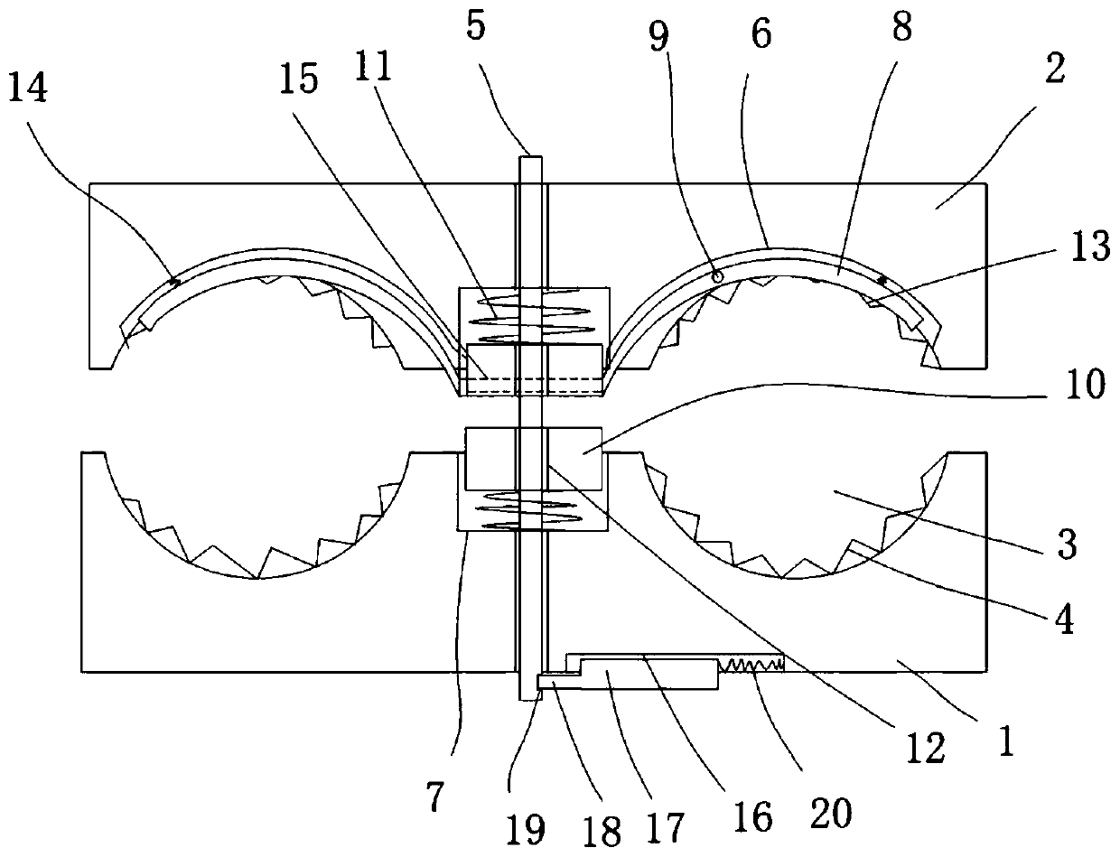
[0027] Such as figure 1 The shown rod pressing type power connection fixture includes a pressure seat 1 and a gland 2, and an arc-shaped wire groove 3 is arranged on the crimping surface of the pressure seat 1 and the gland 2, and on the pressure seat 1 and the arc-shaped wire groove 3 of the gland 2 are evenly provided with tooth tips 4, the pressure seat 1 and the gland 2 are provided with fastening screws 5, and the pressure seat 1 and the gland 2 are provided with Groove 6, the groove 6 and the arc-shaped wire groove 3 are vertically arranged, and the middle part of the pressure seat 1 and the gland 2 is provided with a pressure plate groove 7, and the pressure plate groove 7 is connected with the arc-shaped wire groove 3 are parallel to each other, an arc-shaped warping rod 8 is arranged in the groove 6, the middle part of the arc-shaped warping rod 8 is connected in the groove 6 through a rotating shaft 9, and a pressure plate body is arranged in the pressure plate groov...

Embodiment 2

[0039] Such as figure 1 The shown rod pressing type power connection fixture includes a pressure seat 1 and a gland 2, and an arc-shaped wire groove 3 is arranged on the crimping surface of the pressure seat 1 and the gland 2, and on the pressure seat 1 and the arc-shaped wire groove 3 of the gland 2 are evenly provided with tooth tips 4, the pressure seat 1 and the gland 2 are provided with fastening screws 5, and the pressure seat 1 and the gland 2 are provided with Groove 6, the groove 6 and the arc-shaped wire groove 3 are vertically arranged, and the middle part of the pressure seat 1 and the gland 2 is provided with a pressure plate groove 7, and the pressure plate groove 7 is connected with the arc-shaped wire groove 3 are parallel to each other, an arc-shaped warping rod 8 is arranged in the groove 6, the middle part of the arc-shaped warping rod 8 is connected in the groove 6 through a rotating shaft 9, and a pressure plate body is arranged in the pressure plate groov...

Embodiment 3

[0051] Such as figure 1 The shown rod pressing type power connection fixture includes a pressure seat 1 and a gland 2, and an arc-shaped wire groove 3 is arranged on the crimping surface of the pressure seat 1 and the gland 2, and on the pressure seat 1 and the arc-shaped wire groove 3 of the gland 2 are evenly provided with tooth tips 4, the pressure seat 1 and the gland 2 are provided with fastening screws 5, and the pressure seat 1 and the gland 2 are provided with Groove 6, the groove 6 and the arc-shaped wire groove 3 are vertically arranged, and the middle part of the pressure seat 1 and the gland 2 is provided with a pressure plate groove 7, and the pressure plate groove 7 is connected with the arc-shaped wire groove 3 are parallel to each other, an arc-shaped warping rod 8 is arranged in the groove 6, the middle part of the arc-shaped warping rod 8 is connected in the groove 6 through a rotating shaft 9, and a pressure plate body is arranged in the pressure plate groov...


PUM


Abstract

The invention discloses a warped rod compression type power continuation fixture and a working method thereof. The fixture includes a pressing seat and a gland. Arc-shaped wiring troughs are arranged in crimping surfaces of the pressing seat and the gland. The arc-shaped wiring troughs of the pressing seat and the gland are uniformly provided with tooth tips. The pressing seat and the gland are provided with a fastening screw thereon. Grooves are arranged in the pressing seat and the gland. The grooves are arranged perpendicularly to the arc-shaped wiring troughs. Pressing plate grooves are arranged in middle parts of the pressing seat and the gland. Arc-shaped warped rods are arranged in the grooves. The middle parts of the arc-shaped warped rods are connected in the grooves by rotating shafts. Pressing plate bodies are arranged in the pressing plate grooves. Springs are arranged between the pressing plate bodies and the pressing plate grooves. One end of each arc-shaped warped rod is fixed on the side of the corresponding pressing plate body. Screw holes are arranged in the pressing plate bodies. The fastening screw is arranged in the screw holes. The structure of the invention is reasonable, the stability and reliability of the connection of a cable can be effectively ensured, the cases of looseness or detachment do not occur easily, and the using stability is high, adaptability and practicability are high.

Description

technical field [0001] The invention belongs to the technical field of electric equipment, and in particular relates to a rod pressing type electric power connection fixture and a working method of the rod pressing type electric power connection fixture. Background technique [0002] In the construction of power lines, the cables need to be branched or connected during use. At this time, it is necessary to use power fittings to connect the two wires together to ensure the conduction of the cables. However, there is currently no tool that can connect the two wires. , and due to the different diameters of the cables, the applicability and practicality are also limited. [0003] Therefore, the above-mentioned problems need to be solved urgently. Contents of the invention [0004] Purpose of the invention: In order to overcome the deficiencies of the prior art, the purpose of the present invention is to provide a rod-tightening type power extension fixture and a working metho...

Claims


Application Information

Patent Timeline
Patent Type & Authority Patents(China)
IPC IPC(8): H02G3/06H02G1/14C08L27/12C08L29/14C08L91/00C08K13/04C08K7/04C08K3/28C08K3/22C08K5/20
CPCC08K2003/2296C08K2003/282C08L27/12C08L29/14C08L2203/20C08L2205/03H02G1/14H02G3/0691C08L91/00C08K13/04C08K7/04C08K3/28C08K3/22C08K5/20
Inventor 卞毓平
Owner ELECTRIC POWER RESEARCH INSTITUTE, CHINA SOUTHERN POWER GRID CO LTD
Why Eureka
Try Eureka