
Tensile force adjusting device for mechanical arms

A technology of adjusting device and manipulator, which is applied to manipulators, program-controlled manipulators, manufacturing tools, etc., can solve the problems of shortening the life of adjusting devices, decreasing the tension force of manipulators, and not being particularly convenient to adjust the size of the tension force.

Active Publication Date: 2017-12-22
利辛县宝隆橡塑密封件有限责任公司
View PDF4 Cites 0 Cited by
  • Summary
  • Abstract
  • Description
  • Claims
  • Application Information

AI Technical Summary

Problems solved by technology

[0007] In order to overcome the shortcomings of the existing technical solutions, the present invention provides a tension adjustment device for the mechanical arm, which not only solves the problem that when the traditional mechanical arm is in use, it is often caused by the long-term work between the two mechanical arms. The tension between the mechanical arms decreases, resulting in the unstable work of the mechanical arms, resulting in a decrease in work efficiency. It also solves the problem that the adjustment of the tension force is not particularly convenient when the existing mechanical arms are in use, making workers When we use the mechanical arms, we often need to spend more time to adjust the tension between the mechanical arms, and it also solves the problem that when the existing mechanical arms are in use, the tension adjustment device often The difficulty of reducing the life of the adjustment device due to rusting of the adjustment device due to long-term contact with oxygen and water

Method used


Image

  • Tensile force adjusting device for mechanical arms
  • Tensile force adjusting device for mechanical arms
  • Tensile force adjusting device for mechanical arms

Examples


Embodiment

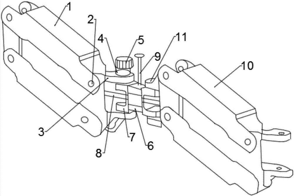
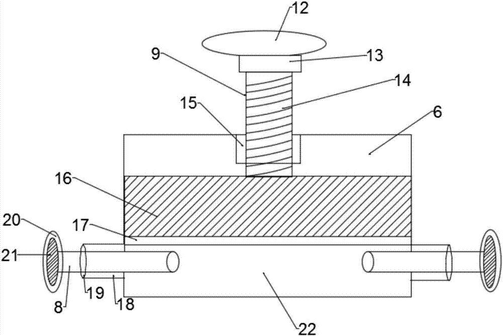
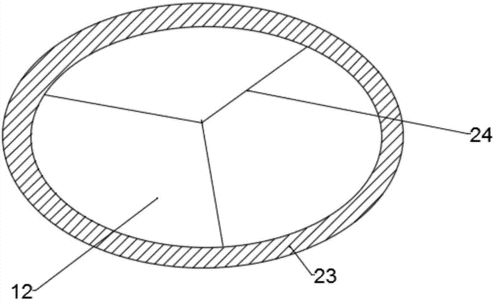
[0027] Such as figure 1 , figure 2 and image 3 As shown, the present invention provides a tension adjusting device for a mechanical arm, comprising a left mechanical arm 1 and a right mechanical arm 10, the right end of the left mechanical arm 1 is provided with a connecting hole 2, and the right end of the connecting hole 2 is provided with a left The connecting arm 3, the left connecting arm 3 is provided with a fixing screw 4, the left end of the right mechanical arm 10 is provided with a right connecting arm 11, and a connecting body 6 is arranged between the left connecting arm 3 and the right connecting arm 11, Link hinges 7 are arranged at both ends of the connecting body 6, a tension rod 8 is arranged inside the connecting body 6, a tension adjusting rod 9 is arranged above the connecting body 6, and a tension adjusting rod 9 is arranged above the connecting body 6. A fixed end 13 is provided, a turntable 12 is arranged above the fixed end 13, a thread 14 is provid...


PUM


Abstract

The invention discloses a tensile force adjusting device for mechanical arms. The tensile force adjusting device comprises the left mechanical arm and the right mechanical arm. Connecting holes are formed in the right end of the left mechanical arm. The right ends of the connecting holes are provided with a left connection arm. A fixing screw is arranged in the left connection arm. A right connection arm is arranged at the left end of the right mechanical arm. A connecting body is arranged between the left connection arm and the right connection arm. Link hinges are arranged at the two ends of the connecting body. A tensioning rod is arranged inside the connecting body. A tensile force adjusting rod is arranged above the connecting body. A fixing end is arranged above the tensile force adjusting rod. A rotary table is arranged above the fixing end. A screw hole is formed in the upper surface of the connecting body. The lower end of the tensile force adjusting rod is connected with a compression plug. Extendable holes are formed in the two ends of the bottom side face of the connecting body. Supporting rods are arranged in the middle of the rotary table. The problem that working efficiency of a traditional mechanical arm is lowered is solved, the problem that tensile force of an existing mechanical arm cannot be adjusted conveniently is also solved, and the difficult problem that the service life of an existing tensile force adjusting device is shortened is further solved.

Description

technical field [0001] The invention relates to the field of control mechanical equipment, in particular to a tension adjusting device for a mechanical arm. Background technique [0002] Robotic arms are often used in the automated production process of modern factories. Common robotic arms are inconvenient in terms of stability and flexibility. position, nor can the robotic arm move to a certain position and stop there stably. [0003] The application number is 201320878325.0 and the name is the invention patent of the mechanical arm. The advantage of this invention is that the rear arm of the mechanical arm rotates up and down with one end as the axis, which drives the forearm to move up and down, and the forearm rotates left and right with the hinge joint with the rotary joint as the axis. The balance part can balance the up and down rotation position of the rear arm, and the braking device can balance the left and right rotation position of the forearm. Therefore, the ...

Claims


Application Information

Patent Timeline
IPC IPC(8): B25J9/10B25J9/14
Inventor 张国文张晓芳张锋
Owner 利辛县宝隆橡塑密封件有限责任公司
Learn More