PCB glue dispensing device

A PCB board and glue dispensing device technology, which is applied to the surface coating liquid device, coating, etc., can solve problems such as lamination, poor contact, glue injection amount and glue injection point, etc., and achieve easy use , the effect of simple operation

Inactive Publication Date: 2017-12-26
HUBEI KUANGTONG ELECTRONICS
View PDF0 Cites 7 Cited by
  • Summary
  • Abstract
  • Description
  • Claims
  • Application Information

AI Technical Summary

Problems solved by technology

[0002] The pins of some integrated chips are set on one side. After the integrated chip is soldered to the PCB, the chip is raised so that the bottom surface of the chip cannot be attached to the surface of the PCB. In the process of later debugging and use , the chip will be pressed down, and pressing the chip will cause the chip pins to be lifted and desoldered, resulting in poor contact; the general treatment method is to fill the gap between the chip and the PCB board with glue (such as epoxy resin), Although it can solve the problem of chip desoldering due to pressing, it is generally manual dispensing with a hand-held rubber hose, so it is difficult to grasp the amount and point of glue injection, and the dispensing efficiency is not high.

Method used


Image

  • PCB glue dispensing device
  • PCB glue dispensing device
  • PCB glue dispensing device

Examples


Embodiment Construction

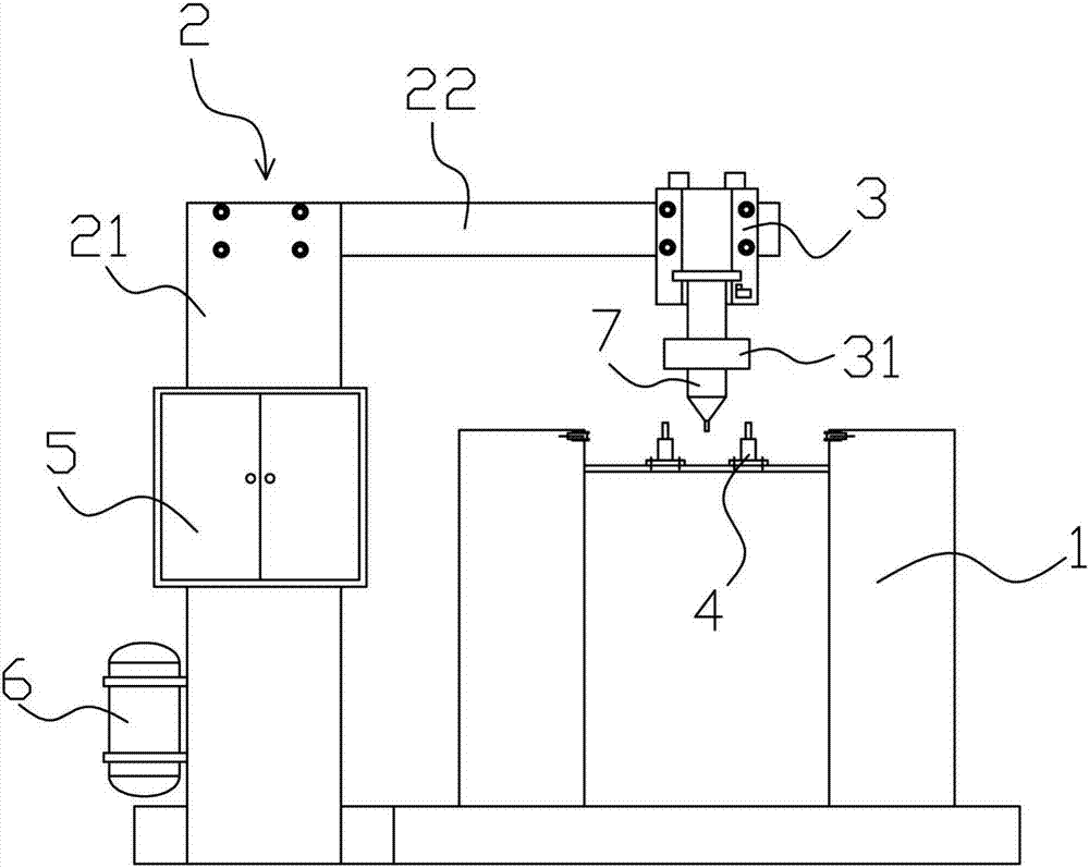
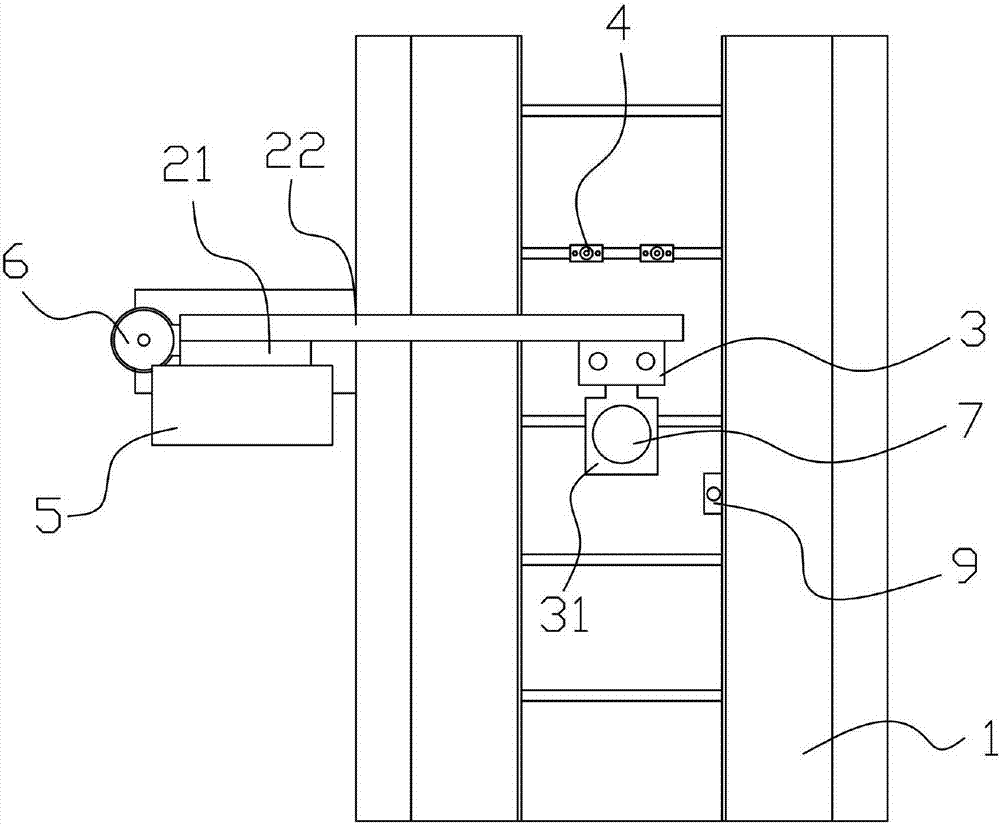
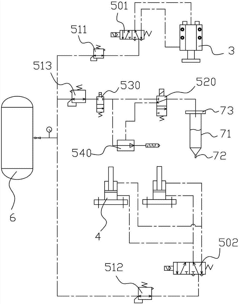
[0018] Such as Figures 1 to 4 Shown: a PCB board dispensing device, including a conveyor 1 for conveying PCB boards, and also includes a frame 2, a control unit 5 and an air source 6, and the frame 2 includes a main beam 21 and a beam 22, and the beam 22 is located above the conveyor 1, the first cylinder 3 is fixed on the beam 22, the clamping block 31 is fixed on the piston rod of the first cylinder 3, and a clamping block 31 is installed in the clamping block 31 for dispensing glue for the PCB board. The rubber hose 7 is installed on the conveyor 1 with the second cylinder 4 and the photoelectric sensor 9; the control unit 5 and the air source 6 are installed on the main beam 21, the photoelectric sensor 9 is connected with the control unit 5, and the control unit 5 is used to control the first The action of the first cylinder 3, the second cylinder 4, the conveyor 1 and the rubber hose 7, the air source 6 provides power for the first cylinder 3, the second cylinder 4 and ...


PUM


Abstract

A PCB board dispensing device, including a conveyor used to transport PCB boards, also includes a frame, a control unit and an air source, the frame includes a main beam and a beam, the beam is located above the conveyor, and fixed on the beam The first cylinder, a clamping block is fixed on the piston rod of the first cylinder, a rubber hose for dispensing glue for the PCB board is installed in the clamping block, and the second cylinder and photoelectric sensor are installed on the conveyor; the control unit And the air source is installed on the main beam, the photoelectric sensor is connected with the control unit, the control unit is used to control the action of the first cylinder, the second cylinder conveyor and the rubber hose, the air source provides power for the first cylinder, the second cylinder and the rubber hose, The invention can efficiently, quantitatively and accurately dispense glue for PCB boards.

Description

technical field [0001] The invention relates to an installation device for electronic parts, in particular to a PCB board dispensing device. Background technique [0002] The pins of some integrated chips are set on one side. After the integrated chip is soldered to the PCB, the chip is raised so that the bottom surface of the chip cannot be attached to the surface of the PCB. In the process of later debugging and use , the chip will be pressed down, and pressing the chip will cause the chip pins to be lifted and desoldered, resulting in poor contact; the general treatment method is to fill the gap between the chip and the PCB board with glue (such as epoxy resin), Although it can solve the problem of chip desoldering due to pressing, it is generally hand-held to dispense glue, so it is difficult to grasp the amount and point of glue injection, and the dispensing efficiency is not high. Contents of the invention [0003] The technical problem to be solved by the present i...

Claims


Application Information

Patent Timeline
Patent Type & Authority Applications(China)
IPC IPC(8): B05C5/02B05C11/10B05C13/02
CPCB05C5/0225B05C11/1013B05C13/02
Inventor 杨洁
Owner HUBEI KUANGTONG ELECTRONICS
Why Eureka
Try Eureka