
Photoelectric sensor device

A photoelectric sensing and equipment technology, applied in the field of sensors, can solve the problems of equipment placement limitation, increase equipment volume, affect equipment portability, etc., and achieve the effect of convenient detection process, expansion of use scope, and expansion of application scope.

Inactive Publication Date: 2017-12-29
MINNAN INST OF SCI & TECH
View PDF7 Cites 3 Cited by
  • Summary
  • Abstract
  • Description
  • Claims
  • Application Information

AI Technical Summary

Problems solved by technology

However, most of the existing slot-type photoelectric sensors are fixed sensors, and the distance between the two photoelectric gates of the sensor cannot be adjusted according to needs, which limits the scope of application of a single type of slot-type photoelectric sensor; in addition, the existing In order to detect flying objects, the trough-type photoelectric sensor needs to be equipped with a special adjustment bracket, which not only increases the volume of the device, but also limits the placement of the device, and it is time-consuming and laborious to debug the device, which affects the operability of the device. ; In addition, the portability of the device is seriously affected after the device is too large

Method used


Image

  • Photoelectric sensor device
  • Photoelectric sensor device
  • Photoelectric sensor device

Examples


Embodiment

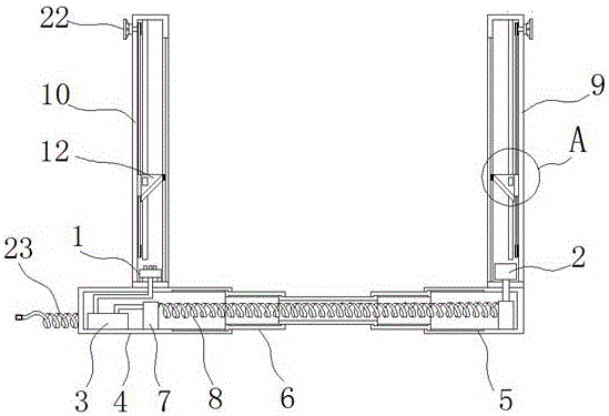
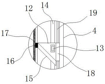
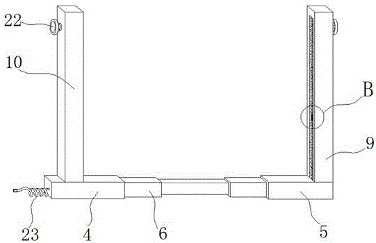
[0021] Such as Figure 1-5 As shown, a photoelectric sensing device includes a transmitter 1, a receiver 2 and a detection circuit board 3, and the detection circuit board 3 is arranged inside the casing, and the casing is provided with a first sleeve 4 and a second sleeve opposite to each other by an opening. The detection circuit board 3 is arranged inside the first sleeve 4, and the first sleeve 4 and the second sleeve 5 are connected by a telescopic tube 6, and the insides of the first sleeve 4 and the second sleeve 5 are both There is a cavity for accommodating the telescopic tube 6, the first sleeve 4 and the second sleeve 5 are also provided with a wire fixing seat 7, and a helical wire 8 is connected between the two wire fixing seats 7, and the helical wire One end of 8 is electrically connected to the detection circuit board 3, and the other end of the spiral wire 8 is electrically connected to the receiver 2 that passes through the second sleeve 5 and is arranged in ...


PUM


Abstract

The invention, which belongs to the technical field of the sensor, especially relates to a photoelectric sensor device comprising a transmitter, a receiver and a detection circuit board. The detection circuit board is arranged inside a housing; and the housing is formed by a first sleeve and a second sleeve, wherein the openings of the first sleeve and the second sleeve are opposite. The detection circuit board is arranged inside the first sleeve; the first sleeve and the second sleeve are connected by a telescopic tube; and cavities for accommodating the telescopic tube are formed in the first sleeve and the second sleeve. Besides, wire fixation seats are also arranged in the first sleeve and the second sleeve; a spiral wire is connected between the two wire fixation seats; one end of the spiral wire is connected with the detection circuit board electrically; and the other end of the spiral wire penetrates the second sleeve and is connected electrically with the receiver arranged in a first vertical tube. The photoelectric sensor device has the following advantages: the portability of the device is enhanced; the detection process is implemented conveniently; and the application range of the device is extended effectively.

Description

technical field [0001] The invention belongs to the technical field of sensors, and in particular relates to a photoelectric sensing device. Background technique [0002] A photoelectric sensor is a sensor that uses a photoelectric element as a detection element. In general, a photoelectric sensor consists of three parts, which are divided into: a transmitter, a receiver, and a detection circuit. Since the application of photoelectric sensors involves a wide range of fields, its research and development have attracted great attention in the world, and countries are competing to research and develop and cause fierce competition. From the initial military application to civil affairs, and it is closely related to our life, it should be said that modern life is inseparable from the participation of photoelectric sensors, such as fax machines, copiers, scanners, printers, garage door openers, LCD monitors, color sensors, etc. Meters, spectrometers, automotive and medical diagno...

Claims


Application Information

Patent Timeline
Patent Type & Authority Applications(China)
IPC IPC(8): G01D5/28
CPCG01D5/285
Inventor 王丽君陈志远郑亚玉李和仙林二妹彭川来张云鹏
Owner MINNAN INST OF SCI & TECH
Learn More