Water treatment system and water treatment method

A water treatment system and water treatment technology, applied in water/sewage treatment, natural water treatment, water treatment parameter control, etc., can solve the problems of huge energy and cost, achieve stable water quality, high reduction effect, and suppress toxicity Effect

Active Publication Date: 2018-01-02
MITSUBISHI ELECTRIC CORP
View PDF24 Cites 5 Cited by
  • Summary
  • Abstract
  • Description
  • Claims
  • Application Information

AI Technical Summary

Problems solved by technology

In either method, enormous energy and cost are required

Method used


Image

  • Water treatment system and water treatment method
  • Water treatment system and water treatment method
  • Water treatment system and water treatment method

Examples


Embodiment approach 1

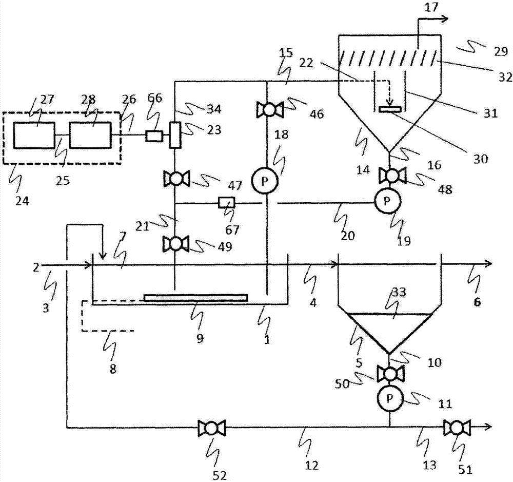
[0041] figure 1 It is a schematic diagram which shows an example of the water treatment system concerning Embodiment 1. The water treatment system uses the standard activated sludge method in the biological treatment process.

[0042] The water treatment system includes structural elements such as the aeration tank 1 as an example of a microbial treatment unit configured to treat water using microorganisms. The aeration tank 1 contains aerobic microorganisms that can utilize organic matter as a substrate. Moreover, the aeration tank 1 is connected with the waste water introduction path 3 which accommodates the waste water 2, and the outflow path 4 which accommodates the outflow water from the aeration tank 1. As shown in FIG. In addition, the outflow path 4 is also connected to the sedimentation tank 5 , and the outflow water from the aeration tank 1 is transferred to the sedimentation tank 5 . The sedimentation tank 5 is connected to a treated water discharge channel 6 , a...

Embodiment approach 2

[0163] Figure 11 It is an example of the apparatus structure of this invention when "standard activated sludge process" is applied to a biological treatment process.

[0164] exist Figure 11 Among them, the sludge transfer pipe 15 is connected to the sludge return pipe 12 . In addition, in Figure 7 Among them, the sludge transfer pump 18 is not provided. Otherwise with figure 1 same.

[0165] In Embodiment 2, the separated sludge 33 accumulated in the settling tank 5 , that is, microorganisms flowing out from the aeration tank 1 is transferred to the ozone reaction tank 14 to perform ozone treatment. When the sludge transfer process starts, the valve 46 on the sludge transfer pipe 15 is opened, and the microbial mixture 7 flowing through the sludge return pipe 12 is transferred to the ozone reaction tank 14 through the sludge transfer pipe 15 .

[0166] The transfer amount can be managed in the same way as in the first embodiment. Other operations are the same as in ...

Embodiment approach 3

[0168] Figure 12 This is an example of the device structure of the present invention when the "biofilm method" is applied to the biological treatment process. exist Figure 12 In the aeration tank 1, a microbial carrier 37 is dropped. Besides that, with Figure 11 (Embodiment 2) is the same.

[0169] The purpose of the microbial carrier thrown into the aeration tank is to attach microorganisms to the surface and maintain a high biomass in the aeration tank. Such a biological treatment method is generally called "biofilm method". In the case of not adding a carrier, that is, in the case of the "standard activated sludge method" described in Embodiment 1, the floating microorganisms use the organic matter in the wastewater to purify the wastewater, but in the biofilm method, after passing The difference is seen in the purification of microorganisms attached to and fixed on the surface of the carrier. However, it is common to purify wastewater using microorganisms. In addi...


PUM


Abstract

This water treatment system comprises: a biotreatment step in which an organic waste liquid is treated by microbial action; an ozone gas production step in which an ozone gas is evolved; a sludge transfer step in which some of a microorganism-mixed liquid in the biotreatment step is withdrawn and transferred; an ozone treatment step in which ozone is brought into contact with the transferred portion of the microorganism-mixed liquid; and a treated-liquid return step in which the treated liquid that has undergone the ozone treatment is returned from the ozone treatment step to the biotreatmentstep. The microorganisms which have agglomerated and remain undecomposed after the ozone treatment are separated and concentrated, and the undecomposed microorganism agglomerates having been separatedand concentrated are selectively subjected to the ozone treatment.

Description

technical field [0001] The present invention relates to a water treatment system and a water treatment method for treating water containing organic substances. Background technique [0002] Conventionally, a water treatment system using a method of treating water such as waste water using microorganisms such as a standard activated sludge method is known. In such a water treatment system, treatment for purifying water is performed by using microorganisms capable of consuming organic substances as substrates, and consuming the microorganisms using organic substances in water as substrates. [0003] When microorganisms consume organic matter in water along with water treatment, microorganisms in water proliferate. For example, in the standard activated sludge method, although a settling tank is provided after the aeration tank to retain the microorganisms flowing out of the aeration tank, the microorganisms flowing out of the aeration tank may exceed the sedimentation level i...

Claims


Application Information

Patent Timeline
Patent Type & Authority Applications(China)
IPC IPC(8): C02F3/12B01D53/04C02F1/44C02F11/06
CPCC02F11/06B01D53/66B01D2253/106B01D2257/106C02F2103/32C02F2103/346C02F1/78C02F3/1221C02F3/1252C02F3/1268C02F3/26C02F2201/782C02F2203/006C02F2209/40Y02W10/10B01D53/04C02F1/44C02F2101/30
Inventor 今村英二明田川恭平安永望
Owner MITSUBISHI ELECTRIC CORP
Why Eureka
Try Eureka