A connector for floor splicing

A technology for connectors and floors, which is applied in the direction of buildings, floors, and building structures, can solve problems such as troublesome movements, unrecoverable seams, and reduced connection effects of metal parts, so as to achieve a firm combination

Active Publication Date: 2019-09-17
倡创(上海)咨询管理事务所
View PDF5 Cites 0 Cited by
  • Summary
  • Abstract
  • Description
  • Claims
  • Application Information

AI Technical Summary

Problems solved by technology

[0002] The existing floor needs to be spliced ​​when it is laid, but the existing structure is connected through the connection structure of the floor itself. When the floor is laid to the edge of the room, this action is extremely troublesome. At the same time, due to the possibility of sliding between the planks, the range of deformation is very large. Often, the seam between the front and rear floors gradually expands, and the seam It cannot be recovered. At the same time, when the floor expands, there is not enough supporting force to cause the position of the seam to protrude, and the metal parts of the prior art peripherals are simply connected, but this method is to damage the floor. Integrity is at the expense of the firmness of the splicing between each other. Obviously, when this purely rigid structural part plays a role due to the deformation of the floor, its own fatigue will also increase, which reduces the connection effect of the metal parts and at the same time It will in turn damage the floor

Method used


Image

  • A connector for floor splicing
  • A connector for floor splicing

Examples


Embodiment Construction

[0018] The present invention will be described in further detail below in conjunction with the accompanying drawings.

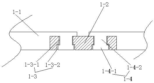
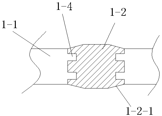
[0019] Such as Figure 1 to Figure 2 As shown, the embodiment of the present invention includes a rigid section 1-1 arranged at both ends and an elastic section 1-2 arranged in the middle, the length of the rigid section 1-1 is greater than the length of the elastic section 1-2, and the elastic section 1-2 is set As for the locking hole 1-3, one end of the rigid section 1-1 is provided with a locking bolt 1-4 connected to the locking hole 1-3, and the insertion directions of the locking holes 1-3 arranged at both ends of the elastic section 1-2 are the same. The clamp 1-4 includes a clamp head 1-4-1 disposed at the end and a clamp body 1-4-2 disposed between the rigid section 1-1 and the clamp head 1-4-1. The clamping hole 1-3 is a through hole, and the clamping hole 1-3 includes an insertion section 1-3-1 and a buckle section 1-3-2, and the diameter of the ...


PUM


Abstract

A connecting piece for splicing of floors comprises rigid sections arranged at the two ends and an elastic section arranged in the middle. The length of each rigid section is larger than that of the elastic section. Clamping holes are formed in the elastic section. Clamping bolts connected with the clamping holes are arranged at one ends of the rigid sections. The inserting directions of the two clamping holes of the elastic section are the same. The structure is simple; connecting of the floors is fastened through the rigid sections; and through the elastic section, when a gap between the floors is small, the distance between the rigid sections at the two ends is decreased so as to adapt to the decreased gap, and when the gap becomes larger, the rigid sections at the two ends are tightened to enable the gap of the floors to recover gradually.

Description

technical field [0001] The invention relates to the field of floor accessories, in particular to a connector for floor splicing. Background technique [0002] The existing floor needs to be spliced ​​when it is laid, but the existing structure is connected through the connection structure of the floor itself. When the floor is laid to the edge of the room, this action is extremely troublesome. At the same time, due to the possibility of sliding between the planks, the range of deformation is very large. Often, the seam between the front and rear floors gradually expands, and the seam It cannot be recovered. At the same time, when the floor expands, there is not enough supporting force to cause the position of the seam to protrude, and the metal parts of the prior art peripherals are simply connected, but this method is to damage the floor. Integrity is at the expense of the firmness of the splicing between each other. Obviously, when this purely rigid structural part plays ...

Claims


Application Information

Patent Timeline
Patent Type & Authority Patents(China)
IPC IPC(8): E04F15/02
Inventor 杨忠卫杨加卫
Owner 倡创(上海)咨询管理事务所
Why Eureka
Try Eureka