Air vent having a control device

A technology for controlling air and air, applied in air handling equipment, transportation and packaging, heating/cooling equipment, etc., can solve problems such as unsealed closure, increased gap between size components, insufficient sealing of air supply channels, etc., to achieve Reduced production cost and simple structure

Inactive Publication Date: 2018-01-05
DR SCHNEIDER KUNSTWERKE
View PDF8 Cites 8 Cited by
  • Summary
  • Abstract
  • Description
  • Claims
  • Application Information

AI Technical Summary

Problems solved by technology

[0005] However, the devices known from the prior art have the disadvantage that the air supply channel can only be closed insufficiently by the rear vertical vanes
Furthermore, the devices known from the prior art in which the operating element is arranged approximately centrally have the disadvantage that the operating element has a relatively large number of parts, which protrude into the flow channel of the air outlet and thus cause the air to additionally, unwanted turn
Therefore, in the prior art, despite the sealing device, it is often not possible to achieve a tight closure because the components of the air outlet have deviations (tolerances) in their dimensions and the gaps between the components also increase with frequent operation.

Method used


Image

  • Air vent having a control device
  • Air vent having a control device
  • Air vent having a control device

Examples


Embodiment Construction

[0056] Components with the same reference numerals in the figures are substantially the same unless otherwise stated. Furthermore, a description of the components of the air outflow device for controlling the air flow that are not necessary for understanding the technical teaching disclosed herein is omitted.

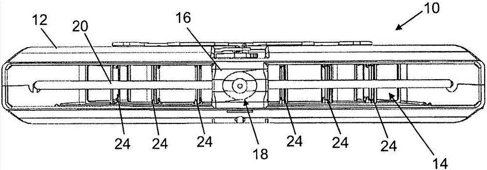
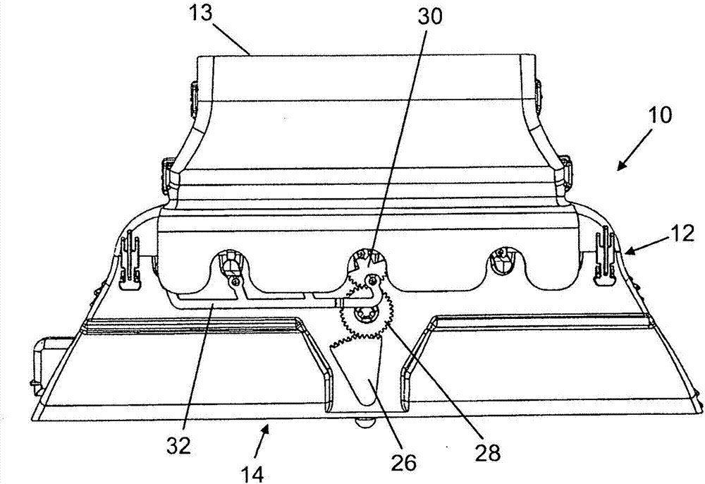
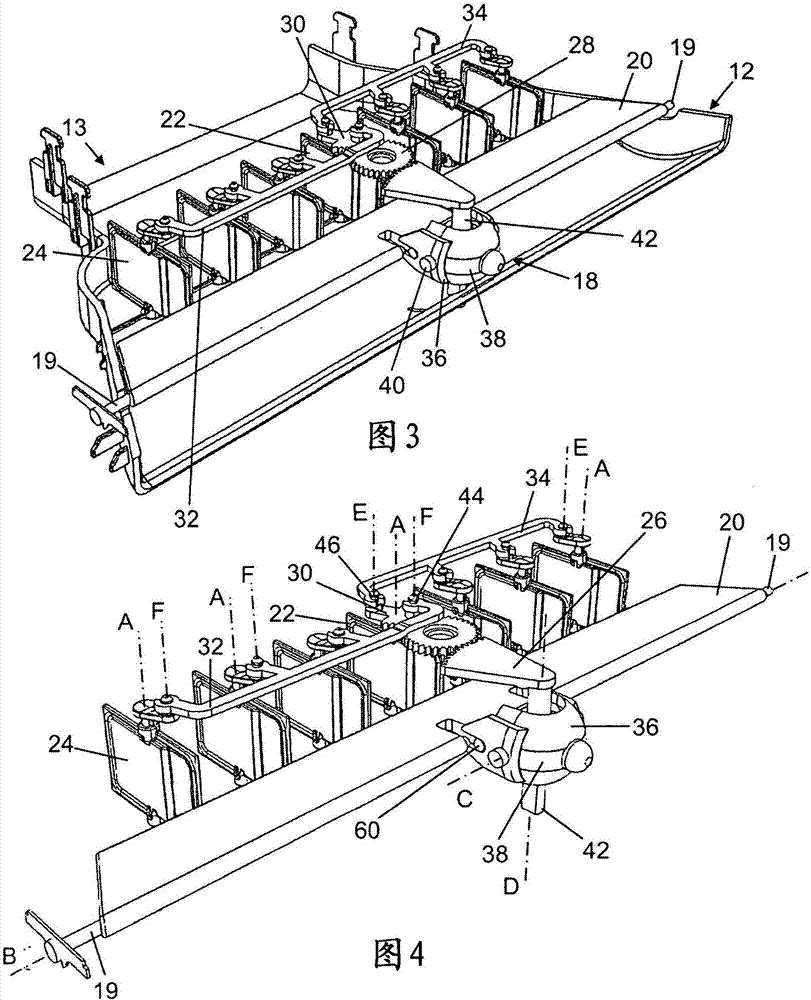
[0057] Figures 1 to 30 The shown air outlet 10 and its components can be arranged, for example, in the region of the center console of a vehicle dashboard. The air outflow device 10 is designed here as a so-called broadband ejector. This means that the air outlet 10 is wider than it is high in the air outlet region 14 . Preferably, the air outlet region 14 has a width of greater than 200 mm, preferably greater than 300 mm.

[0058] In the following description, the terms "rotate" and "pivot" are often used synonymously. For example, the pivotable blade can also be rotated about its axis of rotation and the rotatably mounted actuating element can be pivoted about it...


PUM


Abstract

The invention relates to an air vent having a device for controlling an airstream, wherein the air vent has at least one first control lamella (20) that is pivotably mounted in a housing, and has second lamellae (24) extending orthogonally to the first control lamella (20). For the purpose of controlling the amount and direction of outflowing air, the operating element (18) is pivotable mounted about an axis that extends parallel to the pivot axis of the second lamellae (24), and which is coupled to a first adjustment element (80) and to the first control lamella (20). The first adjustment element (80) has a toothed segment, which is in engagement with a first gearwheel (82) that is rotatably mounted on the housing. The first gearwheel (82) is in engagement with a second adjustment elementthat is arranged on a second control lamella (22) of the second lamellae (24), wherein the second control lamella (22) is coupled with the other second lamellae (24) by way of at least one connectionrod, and the second gearwheel (82) is of spring-mounted design.

Description

technical field [0001] The present invention relates to an air outflow device having a control device for controlling the direction and amount of air flowing out from the air outflow device. In particular, an air dispenser with a control device, which is designed as a so-called single-button operating device, is described. The air outflow device comprises at least one control vane pivotally supported in the housing and a second vane extending perpendicular to the control vane and pivotally supported in the housing, through which the control vane and the second vane can be adjusted from the housing The direction of the air flow out of the body and the amount of outflowing air can additionally be adjusted by means of the second vane. Background technique [0002] Various devices for controlling the air flow are known from the prior art, in which not only the direction but also the quantity of the outgoing air can be adjusted by means of vertical vanes arranged behind the cont...

Claims


Application Information

Patent Timeline
Patent Type & Authority Applications(China)
IPC IPC(8): B60H1/34
CPCB60H1/3421B60H2001/3478
Inventor J·加赖斯D·豪纳J·泽曼
Owner DR SCHNEIDER KUNSTWERKE
Why Eureka
Try Eureka